Community Guides
Lelit Anna PL41EM 2025
A community installation guide for the GaggiMate Pro on a Lelit Anna PL41EM (single boiler, 230V/50Hz, 1050W).
Community Guide
This guide is a community guide which is not maintained by GaggiMate. The author is not affiliated with GaggiMate.Author: Jeff
Last Updated: June 4, 2026
Credits: @maspresso (MOZ) for previously documenting a Lelit Anna install and validating the wiring, @enoflagliqpap for sharing their experience, and the entire GaggiMate Discord community.
Important Notes
High Voltage Safety: Exercise extreme caution when working with high voltage. If you are unsure about any steps, consult a professional technician.Follow Local Codes: Ensure that your work adheres to local electrical codes and standards.
Documentation: Keep a record of your wiring setup for future reference and troubleshooting.
This is a community guide for installing the GaggiMate Pro kit on a Lelit Anna PL41EM (single boiler, 230V/50Hz, 1050W). The Anna shares its base hydraulics with other 57mm group machines from the IMAT OEM family (La Pavoni Casa Bar, Quick Mill 57mm), so most of this guide applies to those as well with minor adjustments.
⚠️ Disclaimer. I’m not an electrician or an expert in this field — just someone who likes to tinker, with a soldering iron, a multimeter, and a healthy dose of caution. This install works on my machine, but this guide may contain mistakes. You are responsible for any damage to your equipment. Double-check every connection, and if in doubt, ask before you wire. ℹ️ Need help? I’m available on the GaggiMate Discord, in the #gaggimate-help channel → thread Lelit Anna [PL41EM - 2025]. Drop your question there and I’ll do my best to answer.Contents
- Kit variant
- What you need
- Lelit Anna reference schematic
- Before you start
- Step 1 — Disassembly and removal
- Step 2 — Hydraulic modifications (Pro version)
- Step 3 — Wiring overview
- Step 4 — High voltage wiring
- Step 5 — Low voltage wiring
- Step 6 — First boot and testing
- Notes and gotchas
- Reference
Kit variant
For the Lelit Anna PL41EM 2025, the Pro kit — M4 K-Type + Pump Fittings (Gaggia Classic Pro/Evo/E24, 2019–2025) variant works out of the box. No custom fittings or cables are required.
What you need
- GaggiMate Pro kit — Pro variant with M4 K-type thermocouple and pump fittings.
- SSR — 40A SSR (Finglai SSR-40DA or equivalent). Often included in the kit.
- Pressure transducer — 1/8” NPT, 0–1.6 MPa. Included with the Pro kit.
- Tools — Multimeter (continuity / Ω mode), Phillips screwdriver, pliers, PTFE tape, optionally a crimping tool.
Lelit Anna reference schematic
The official Lelit wiring diagram for the PL41EM is document 8000059 REV00 (02/11/2022, by M. Garatti and M. Epis). Components used in this guide:
| # | Component | Role |
|---|---|---|
| 1 | IEC plug | Mains inlet |
| 2 | ON/OFF switch | Main power |
| 3 | Safety thermostat 165°C | Boiler safety (keep) |
| 4 | Coffee thermostat 95°C | Brew regulation (removed) |
| 5 | Steam thermostat 125°C | Steam regulation (replaced by thermocouple) |
| 6 | Water pump | OLAB vibratory pump |
| 7 | 3-way solenoid valve | Brew valve |
| 8 | Heating element | Boiler resistance |
| 9 | Pump switch | ”Coffee” button |
| 10 | Hot water / steam switch | ”Steam” button |
| 11 | Ready light | Heater activity indicator (rewired in parallel with the heater) |
| 13 | Anti-jamming filter | 0.33 μF capacitor |
| 14 | ON/OFF light | Indicator |
Before you start
⚡ Mains voltage. The machine runs at 230V. Always unplug the machine from the wall before working inside. Verify with a multimeter that no voltage is present on the IEC pins before touching any wiring.A few tips that save time:
- Cut all the existing zip ties before starting. You will see and reach everything much more easily.
- The original Lelit Faston connectors are extremely tight. Pull them straight along the axis of the terminal, with small left-right rocking motions if needed. Never twist or pull at an angle — you will bend the terminal.
- Take photos of every original connection before disconnecting anything. It saves you twice during the install.
Step 1 — Disassembly and removal
- Open the top cover of the machine. You will see the boiler, the OLAB pump, and the 3-way valve.
- Disconnect the “ready” indicator light (component 11) from its original Faston connectors. Do not throw it away — we will re-wire it in parallel with the heater later (step 4) so it behaves as a heater activity indicator (blinks in sync with the PID, just like on the Gaggia Classic Pro or Rancilio Silvia).
- Remove the 95°C thermostat (component 4) from the boiler. Disconnect both Faston connectors and unscrew it.
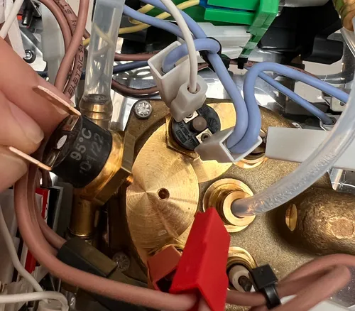
- Remove the 125°C thermostat (component 5) completely. The thermocouple (M4) will be screwed into this exact location later. Leave the location empty for now. On a standard install (e.g. Gaggia Classic), the GaggiMate “Heater bridge” bypasses the lower-temperature (brew) thermostat — the same role that the steam switch normally plays when steaming. In this guide we route the SSR output directly to the heater (see step 6), so neither thermostat sits in the circuit and the heater bridge is not needed. Just remove the 125°C thermostat and set it aside.
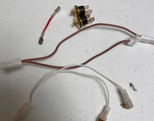
- Disconnect all wires from the Steam and Coffee buttons (components 10 and 9). Keep the Power switch wires untouched. The buttons will be re-wired in low voltage later.
- Remove the original 3-way valve cable completely. This is the only cable from the harness that is fully discarded.
Step 2 — Hydraulic modifications (Pro version)
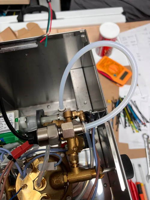
The Pro kit adds a pressure transducer that needs to be teed into the line between the pump and the boiler. On the Anna there is enough space if you reposition the pump slightly.
-
Disconnect the PTFE tube from the pump outlet. It is a push-fitting — push the collar inward, then pull the tube out.
-
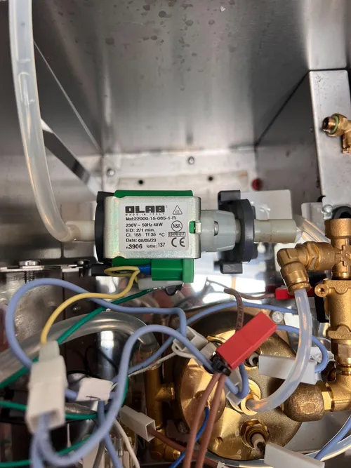
Remove the pump from its rubber mounts (silent blocks). Rotate each mount 180° and reinstall them. This shifts the pump slightly to the left and frees up space for the tee fitting.
-
Screw the white tee fitting onto the pump outlet. The fitting ships with an integrated gasket — do not add PTFE tape to the threads (the gasket already provides the seal, and adding tape can prevent proper seating). Tighten gently — over-torquing will crack the plastic.
ℹ️ I temporarily removed the pressure gauge during installation to have more room to work. You don’t have to — it just makes life easier. -
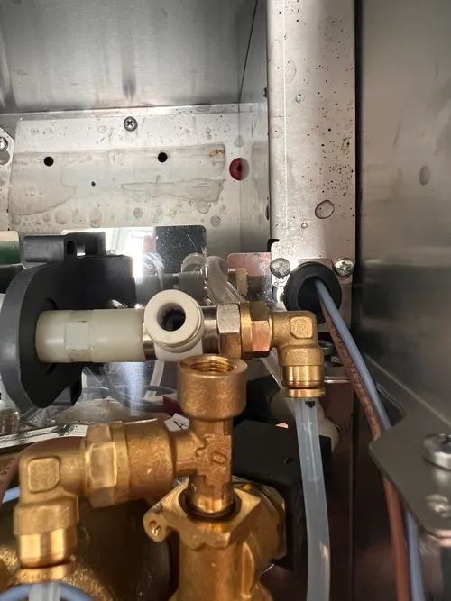
Reconnect the original PTFE tube to the straight outlet of the tee fitting (toward the boiler).
-
Install the pressure transducer’s tube into the side outlet of the tee. The tube is also a push-fitting — insert it firmly until it stops.
Step 3 — Wiring overview
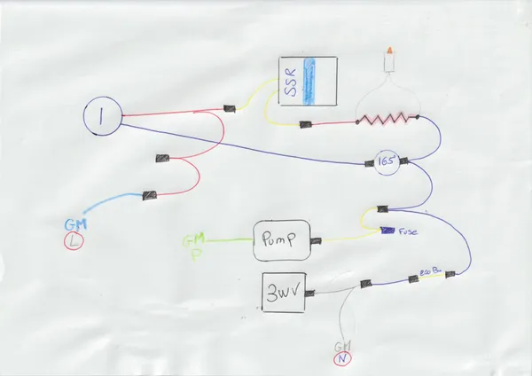
The wiring transforms the machine as follows:
- Heater path: phase now goes through the SSR (controlled by the PCB) instead of the original thermostats.
- Pump and 3-way valve: phase now comes from the PCB outputs (V).
- Buttons: switched from 230V switching to low-voltage signaling to the PCB.
- Thermocouple: replaces the 95°C thermostat for temperature reading.
- Ready light (component 11): re-wired in parallel with the heater so it acts as a heater activity indicator (visible PID blinking pattern).
Here is the simplified wiring diagram (hand-drawn but functional, exactly as shown):
Step 4 — High voltage wiring
-
Plug the kit’s blue “Neutral” cable into an unused terminal on the Power switch output — used here as the GaggiMate Live feed. Leave the original brown phase wire untouched in its existing terminal. The blue cable has a simple male Faston, which fits cleanly into one of the switch terminals freed earlier (e.g. on the Steam row that no longer carries 230V). This keeps the new GaggiMate Live tap out of the heater power path. The other end (10 mm of bare wire) goes to the L terminal of the PCB.
ℹ️ Why blue and not gray? See the swap note in Step 3. The blue cable is used here because it only needs a single male Faston, while the gray cable’s piggyback connector is reserved for the neutral chain (next steps), where combining two Fastons safely matters. -
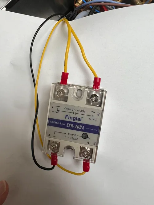
Connect the SSR output (HV) side.
- One yellow “Heater to SSR” cable from the kit goes from the original heater phase wire (the one that used to come from the thermostats) to one of the OUTPUT terminals (1 or 2) of the SSR. Polarity doesn’t matter on the AC side.
- The other yellow “Heater to SSR” cable goes from the other OUTPUT terminal of the SSR directly to the heating element terminal on the boiler.
The SSR now controls the heater. Both the 95°C (component 4) and 125°C (component 5) thermostats are bypassed entirely.
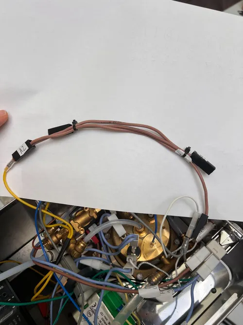 ℹ️ The SSR has two sides: OUTPUT (24–480 VAC) at the top — this is where the 230V load passes through — and CONTROL (3–32 VDC) at the bottom — this is where the PCB signal arrives. Don’t mix them up.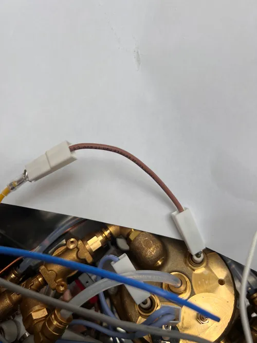
-
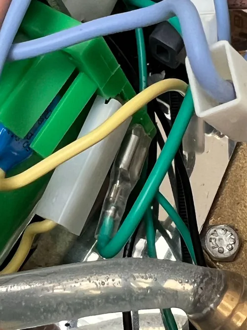
Wire the pump (component 6). Remove the original phase (brown) wire from the pump terminal. Connect the green “Pump” cable from the kit to the same pump terminal. The other end (bare wire) goes to the P terminal of the PCB. The neutral side of the pump stays as it was originally.
-
Wire the 3-way valve (component 7). The 3WV has two terminals — one for phase, one for neutral.
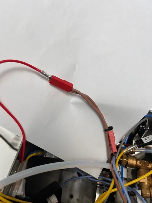
- Phase side: the kit’s red “3-way valve” cable has a male Faston. Plug it into the female Faston that was originally on the Steam button — this wire is already routed to the 3WV phase terminal on its other end, so reusing it saves you from rewiring anything on the 3WV itself. Leave the other Steam button pin empty. The other end of the red kit cable goes to the V terminal of the PCB.
-
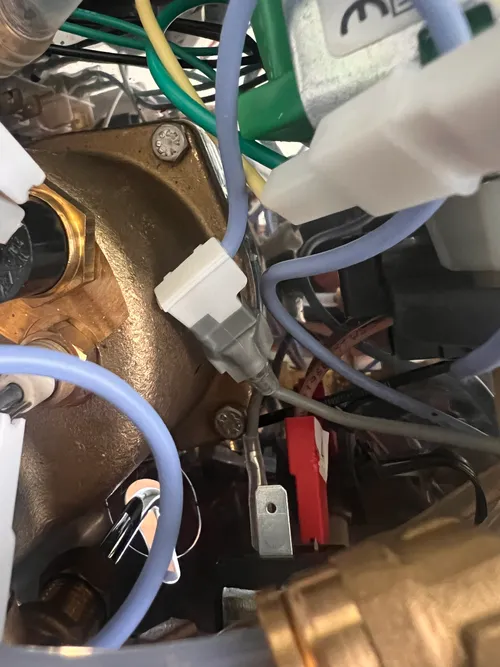
Neutral side: the 3WV neutral is brought back to the PCB through a multi-segment chain that also picks up the pump neutral along the way. From the 3WV neutral terminal towards the N terminal of the PCB, the chain is:
Notes on each segment:
- The gray “Live” kit cable (re-purposed here as Neutral — see Step 3) is plugged onto the 3WV neutral terminal using its piggyback connector, which gives a clean tap for the next segment without any pin-spreading.
- The two blue Faston segments and the Eco bridge (yellow-yellow, otherwise unused on the Lelit Anna) chain the rest of the path back to the PCB.
- The pump neutral joins this chain near the Eco bridge — refer to the wiring diagram for the exact junction point in your build.
-
Connect the PCB neutral (N). The bare-wire end of the second blue cable (the one downstream of the Eco bridge — see previous step) goes to the N terminal of the PCB.
-
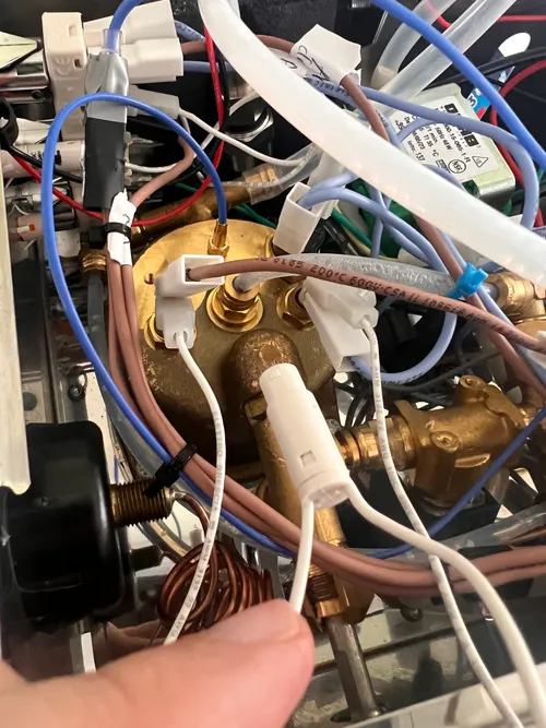
Re-wire the “ready” indicator light (component 11) in parallel with the heater. Use two short jumpers with Faston terminals: connect one terminal of the lamp to the heater phase terminal (i.e. the same point where the yellow “Heater to SSR” cable lands on the boiler) and the other terminal to the heater neutral terminal (the same point as the boiler neutral). The lamp now blinks in sync with the PID duty cycle — exactly like the heater activity light on a Gaggia Classic Pro or Rancilio Silvia. If you prefer a low-voltage indicator, you can alternatively wire it across the SSR control terminals, but the parallel-with-heater wiring is the simpler and more visible option.
At this point, the high-voltage side is complete. The four PCB terminals L, N, P, V are connected, and the ready light is back in service as a heater activity indicator.
Step 5 — Low voltage wiring
-
Thermocouple. Screw the M4 K-type thermocouple into the boiler hole that used to host the
ℹ️ If the temperature reading drops as the boiler heats up, the polarity is reversed — just swap the two wires.95°125°C thermostat (Mounting it here, keeps the probe away from the cold-water inlet). The two wires go to the T+ and T- terminals of the PCB (red to +, black/silver to -). -
SSR signal. The two-wire “SSR signal” cable (yellow + black, JST PH 2P on the PCB side) connects the PCB SSR connector to the CONTROL terminals (3–32 VDC) of the SSR. Yellow to +, black to -. Polarity matters here.
-
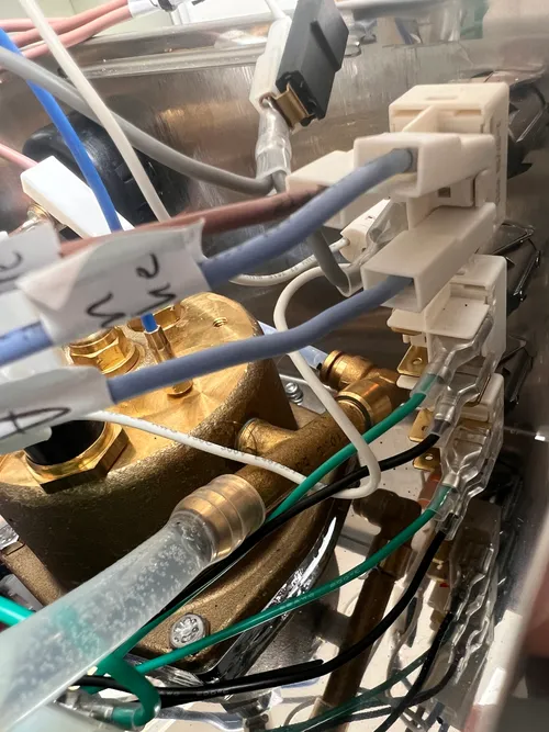
Buttons. Follow the image: plug the green “Steam” wire onto the Steam button and the green “Coffee” wire onto the Coffee button, with their respective black “GND” wires. Polarity doesn’t matter on switch contacts. Refer to the GaggiMate pinout documentation for the PCB side.
-
Pressure transducer (Pro only). The 3-wire transducer cable (red +5V, black GND, signal) plugs into the Pressure terminal block of the PCB.
⚠️ PCB Pro Rev 1.1. If you have a Rev 1.1 Pro PCB, the Pressure header has 4 pins instead of 3 (GND, X, Analog In, +5V). The extra “X” pin is reserved for future use — leave it unconnected. Wire GND, Analog In, and +5V as labeled. -
Screen. Connect the screen power cable (red +3.3V, black GND) and the I2C cable (GND, SDA, SCL) as per the GaggiMate pinout documentation.
Step 6 — First boot and testing
-
Visual inspection. Check every connection. Make sure no bare wire is touching the chassis. Verify the SSR OUTPUT terminals are well screwed (they tend to loosen).
-
Continuity check (machine unplugged).
- Between L of the IEC plug and L of the PCB → should be continuous when the power switch is ON, open when OFF.
- Between N of the IEC plug and N of the PCB → should always be continuous.
-
Power on without water. Plug the machine in. Turn the power switch ON. The PCB should boot — the screen should light up. Do not let the heater run without water; if everything looks normal, turn off and proceed.
-
Fill the tank, prime the system. Run the pump manually from the PCB interface. Water should reach the boiler and exit the steam wand when the steam knob is open.
-
First heat-up. Set a low target (e.g. 80°C) for the first heat-up and watch the temperature reading climb. If it drops instead of rising, swap T+ and T-.
-
PID tuning. As a starting point, the values that worked for @maspresso on his Lelit Anna are:
- P = 61
- I = 0.5
- D = 976
- Setpoint = 93°C
- Offset: see note below.
Your machine may behave slightly differently. The Anna’s boiler is small and the thermocouple is mounted on top of the boiler (former 95°C thermostat location), which is far from the group head — so the temperature read by the PCB will typically be hotter than the actual puck temperature. An Offset of 0°C is therefore unlikely to be correct on this build. The exact value depends on each individual machine (boiler insulation, group head mass, ambient temperature). The recommended approach is to measure the actual puck temperature with a Scace device (or equivalent) and adjust the offset so the PCB setpoint matches the brew temperature you measure at the basket. Expect a non-zero offset.
Notes and gotchas
- Hot water mode is no longer supported. The original Lelit Anna lets you dispense hot water by pressing Steam + Coffee simultaneously with the steam knob open. With GaggiMate, this combined mode is not implemented. Use a separate kettle for tea or hot water.
- The pressure reading lags slightly behind the puck. The pressure transducer is downstream of the pump, so the reading is the pump output pressure — not the puck pressure. This is normal and consistent with other GaggiMate installations.
- Save your spare bridges. The Heater Bridge (red-red) is not used in this install — wiring the SSR directly to the heater bypasses the lower-temp thermostat that the bridge would normally replace. Keep it as a spare. The Eco bridge (yellow-yellow), on the other hand, is used here as part of the 3WV neutral chain (Step 4).
- Door/access for service. Reassemble the machine carefully — the cable routing is tight. Make sure no wire is pinched against the chassis when you close the top cover.
Reference
- Official GaggiMate Pinout
- Official GaggiMate Wiring
- Official Lelit PL41EM wiring diagram (document 8000059 REV00)
If you spot mistakes or have improvements, please open a PR or reach out on Discord. This guide will evolve with community feedback.
Have questions?
Still have questions? Join the Discord!