Step-by-step installation guide for GaggiMate on Gaggia Classic Pro, Evo, and related models.
Important Notes
High Voltage Safety: Exercise extreme caution when working with high voltage. If you are unsure about any steps, consult a professional technician. Follow Local Codes: Ensure that your work adheres to local electrical codes and standards. Documentation: Keep a record of your wiring setup for future reference and troubleshooting.
We’ve prepared a printable guide to label your wires in order to easier follow the install and fix mistakes. You can also just use tape, sticky labels or whatever else you have.
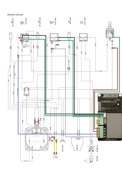
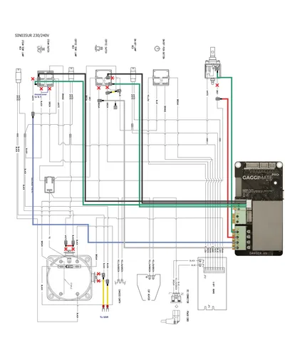
You can check the wiring diagram for additional information.
100 / 120V
240V (with Eco PCB)
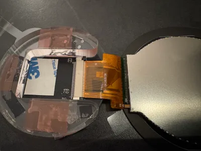
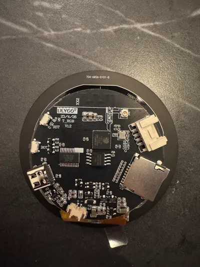
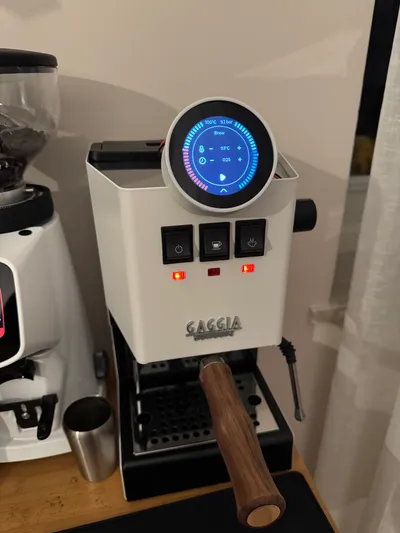
Check the screen
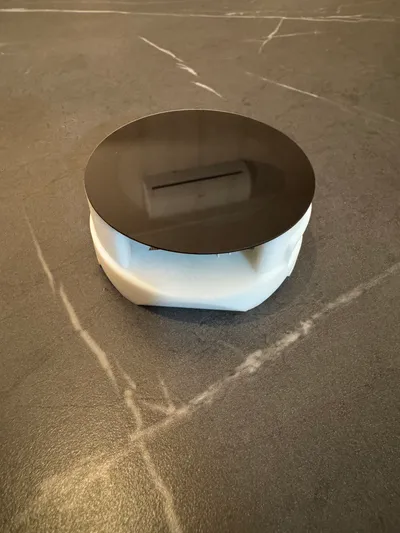
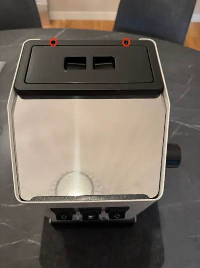
Assemble the printed parts
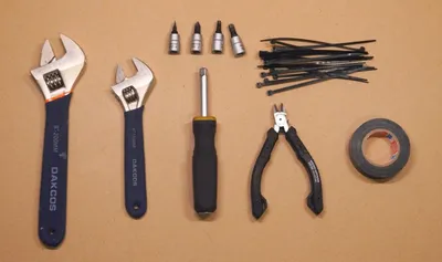
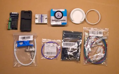
2. Machine preparation
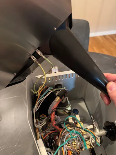
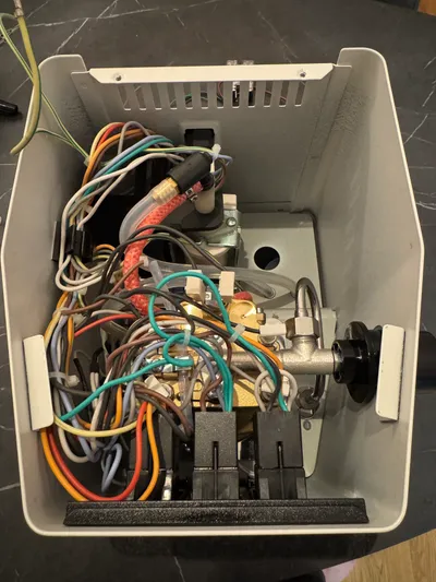
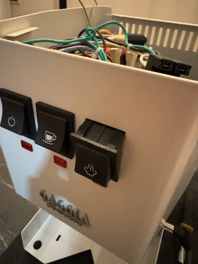
Disassemble the machine
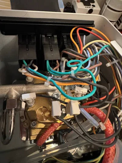
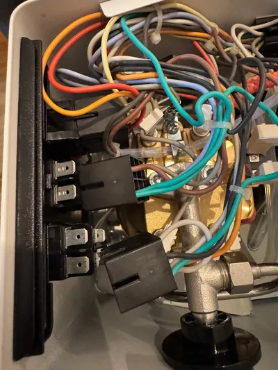
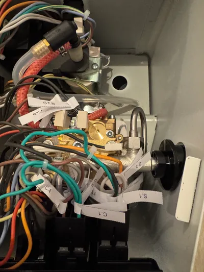
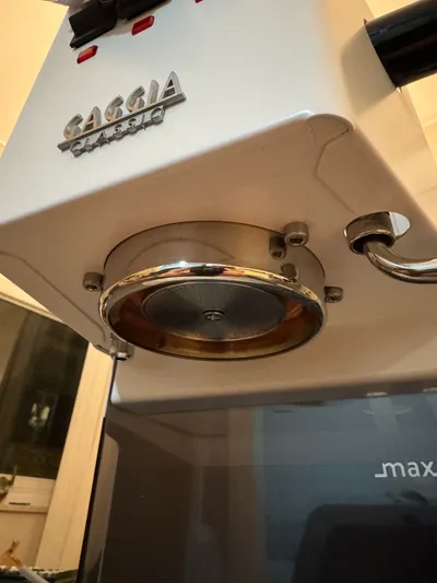
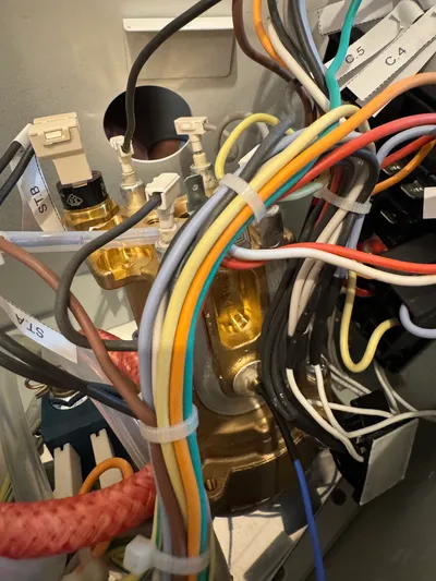
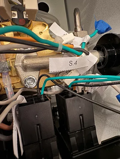
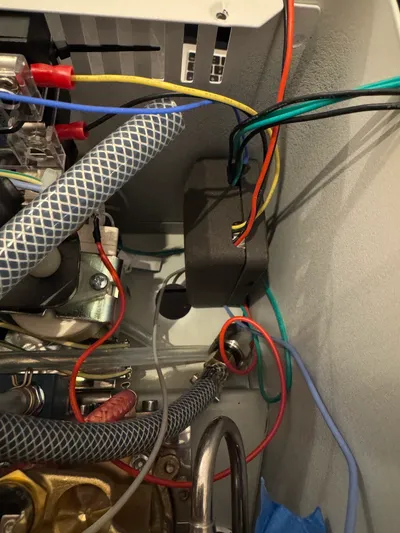
You see an overview of what you should expect above. Make yourself familiar with the layout of the machine. You can use above pictures for reference if you need to check anything. The machine in the pictures is a Gaggia Classic Pro E24 with the Eco PCB. This machine uses monoblock connectors, the wiring is identical to other models though.
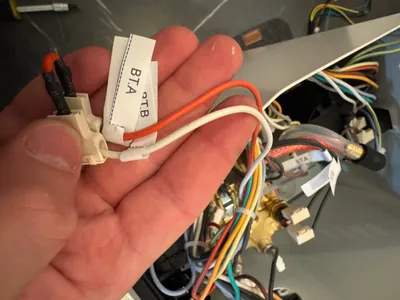
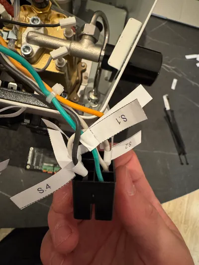
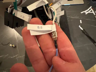
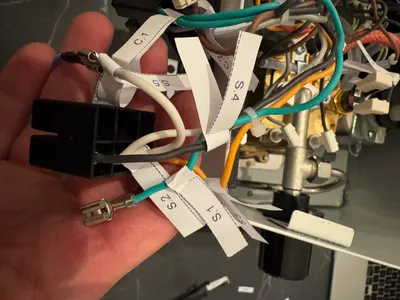
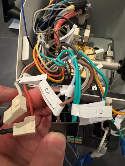
Labeling
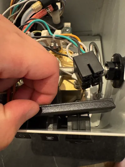
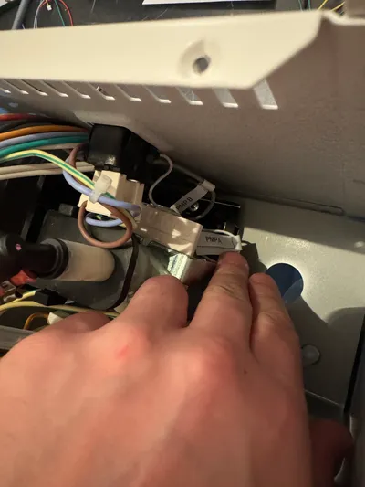
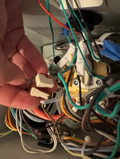
To make labeling a bit easier, especially with the monoblock style connectors you can tilt out the front switches a bit to free those.
If you do not have monoblock connectors tilting the switches might still help with labeling.
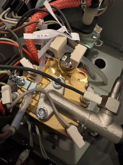
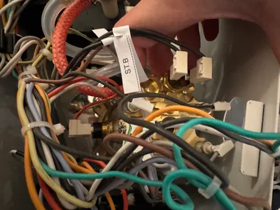
The brew thermostat (BT) sits on the left side of your boiler, the steam thermostat (ST) is the one screwed into the top of the boiler.
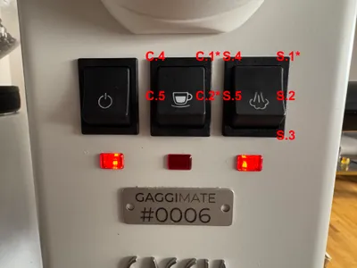
The picture above will show you where these labels should be placed for the button cables. The connections marked with an asterisk are only present on a 240 V machine.
3. Heater modifications
Brew thermostat
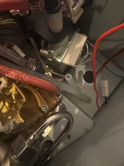
ℹ️ To make uninstallation of the brew thermostat as well of installation of the thermocouple easier, it’s required to loosen the steam valve assembly and unscrew the group head from the case so you’re able to tilt the boiler assembly.
You remove the steam knob and steam wand to gain even more space. After you’re done with the install, re-assemble them before testing the machine.
⚠️ Please make sure you have a secure connection and properly insulate the connection with electrical tape or heatshrink.
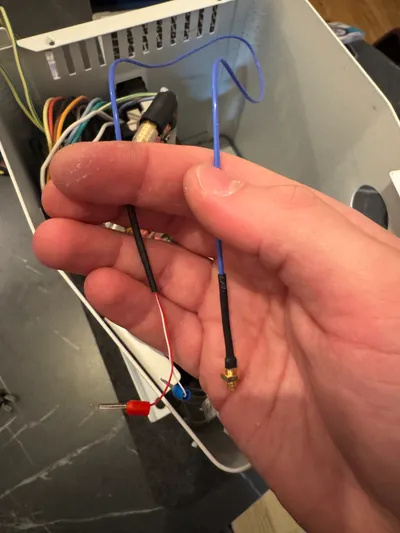
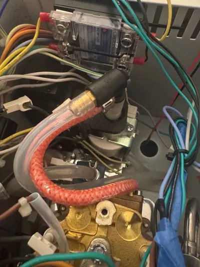
⚠️ Be careful to rotate the wire (folding the wire cautiously helps) as you screw it in and only fasten it hand tight. The thermocouple can easily break off during the screwing process if not handled with care.
It is advised to connect the thermocouple at the end of the installation to the PCB. The red cable is the + connection and the blue is -. See the Pinout for where these are located.
Steam thermostat
⚠️ Please make sure you have a secure connection and properly insulate the connection with electrical tape or heatshrink. ℹ️ You can choose to either remove the steam thermostat or leave it in place. Both ways are just fine.
4. HV Wiring
Steam Switch
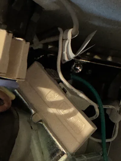
The picture above shows how the steam switch is wired by default. On a machine without the Eco PCB, the green wire labeled S.1 would be missing.
⚠️ On a US machine the double white will be on the other side. Follow the labeling and modifications of the switch positions regardless of that!
⚠️ At this point the wiring of the switch should look like in the above picture for both 120V and 240V machines. Use tape or heatshrink to make sure the connections or removed connectors are properly insulated.
Brew switch
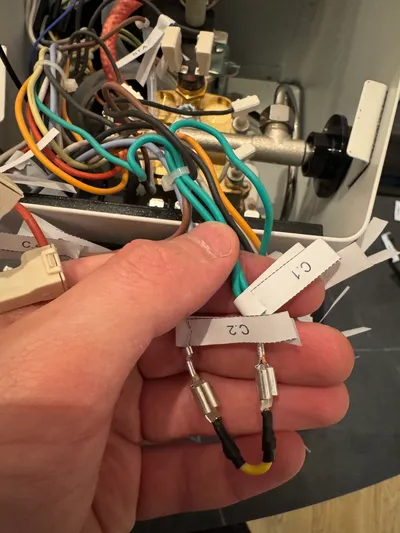
The picture above shows how the brew switch is wired by default. On a machine without the Eco PCB, the wires labeled C.1 and C.2 would be missing.
⚠️ Please make sure you have a secure connection and properly insulate the connection with electrical tape or heatshrink.
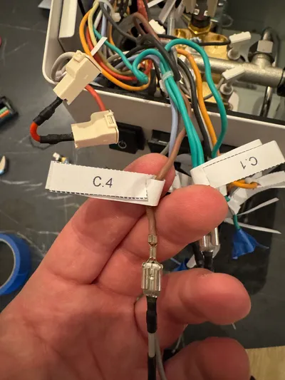
⚠️ Properly insulate the connection and the left over end of the grey cable with electrical tape or heatshrink.
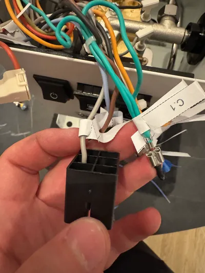
When you’re done, the brew switch (or monoblock connector) should look like this.
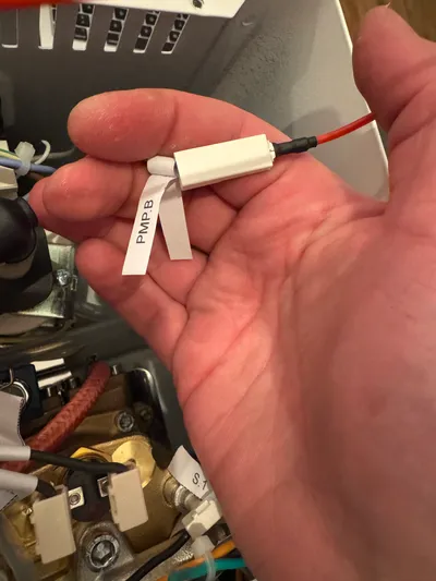
Pump/Three way valve
ℹ️ If you’re installing the pro kit you can do these steps together with # 6.1 where you remove the pump. It makes accessing the wires easier.
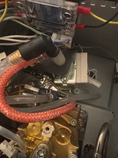
5. Plumbing / Pressure installation
Follow this part only if you’re installing GaggiMate Pro.
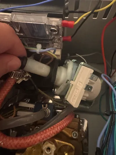
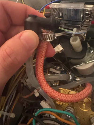
Pump removal
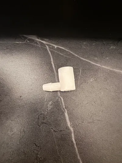
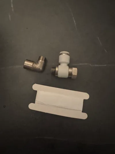
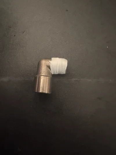
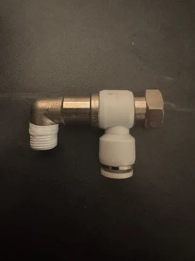
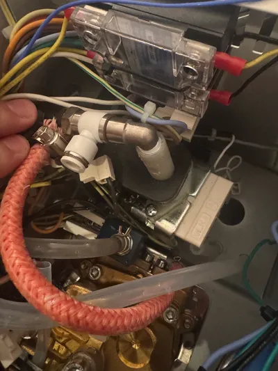
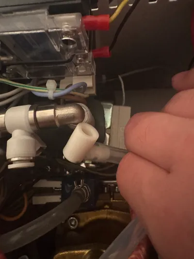
Prepare the new fittings
ℹ️ If you still encounter leaks after installation, add additional layers of PTFE tape. Make sure to get none of the tape inside the water paths as it can block the 3WV and require you to clean it.
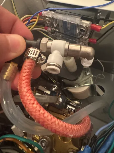
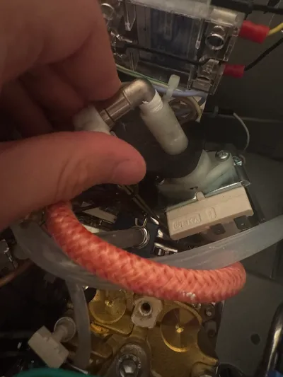
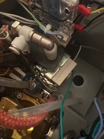
Reassembly
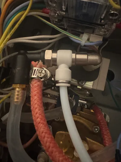
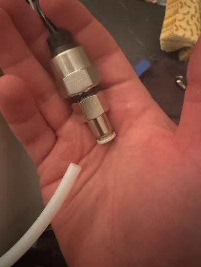
Connecting the transducer
ℹ️ The tube needs to be filled with water, you can either do that manually in this state or bleed it later.
To do it later, run the pump on the machine so it builds some pressure in the boiler, then switch the machine off and with the machine unplugged unscrew the pressure transducer slightly so the air can be released from there.
6. LV Wiring
Button functionality
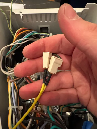
You can choose to retain the functionality of the buttons by using the green/black 4-wire cable from the wiring kit.
⚠️ Make sure never to mix up high and low voltage on the same side of the switch! ℹ️ If you have the monoblock, you should put those back first and then push the connectors in there.
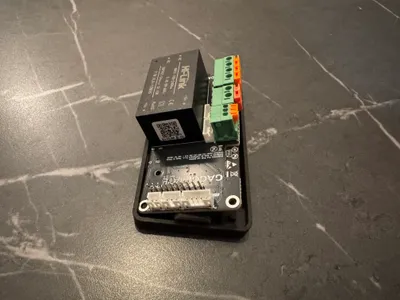
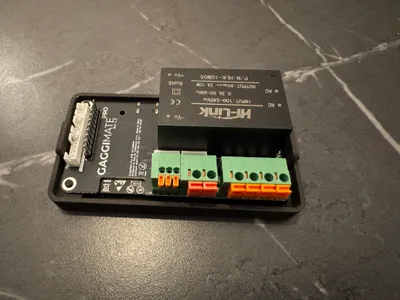
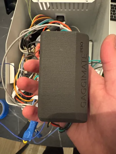
PCB
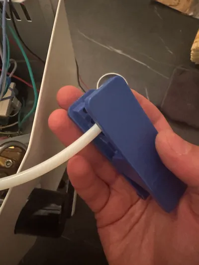
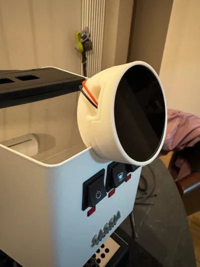
Screen
The cable has enough space to be routed between the cup warmer and casing. The screen casing simply sits on the edge of the housing. Some machines have a slightly thicker paint so if you have trouble getting the casing on, you can use a nail file or sand paper in the groove.
7. Final checks
Testing
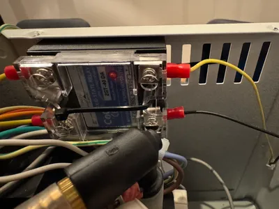
Now is the big moment. Turn on your machine for the first time. The heater should not be heating on power-on and nothing else should be running. You can check if the heater is doing anything by observing the LED on the SSR.
The screen should turn on and show the Standby screen of GaggiMate. Touch the screen once to switch to warmup mode, you should see the current room temperature being displayed and the LED on the SSR will light up indicating it’s heating up.
Pressure test
Before you close up the machine you’ll want to run a pressure test of the system to catch any leaks. For this you can simply run the water mode for a while and see if anything needs fixing.
Final Steps
Reassemble the Machine: Carefully put the panels back on, ensuring that there are no pinched wires.
Important: Conduct a Safety Check: Perform a final inspection to ensure everything is insulated and that there are no exposed wiring connections.
If you have any further questions or need additional clarifications, feel free to go into the Discord and make a help thread or post on our Subreddit.
Congratulations
You have now finished setting up your Gaggia Classic Pro with GaggiMate and can start making coffee.
To check more tasks on your first startup go to First Start.
When you do the first test shots and check the system, remember that you’ll need to have a puck or blind filter in the machine to build any pressure.
If you encounter any problems during the installation check our Troubleshooting guide or open a help thread in #gaggimate-help on Discord.