Installation
Gaggia Classic (1991-2014)
Step-by-step hardware installation guide for GaggiMate on Gaggia Classic machines.
Important Notes
High Voltage Safety: Exercise extreme caution when working with high voltage. If you are unsure about any steps, consult a professional technician.
Follow Local Codes: Ensure that your work adheres to local electrical codes and standards.
Documentation: Keep a record of your wiring setup for future reference and troubleshooting.
Preparation
Safety First! Unplug your machine to ensure there’s no live connections while working on it. Work in a dry environment to prevent electrical hazards.
Read through the entire guide first to make sure any questions will be cleared before the installation. You can always contact us for help or open a help thread on our Discord.
Prepare all parts, materials and tools listed in the sourcing pages. Follow these guides if you haven’t already: Printed Parts and Flashing.
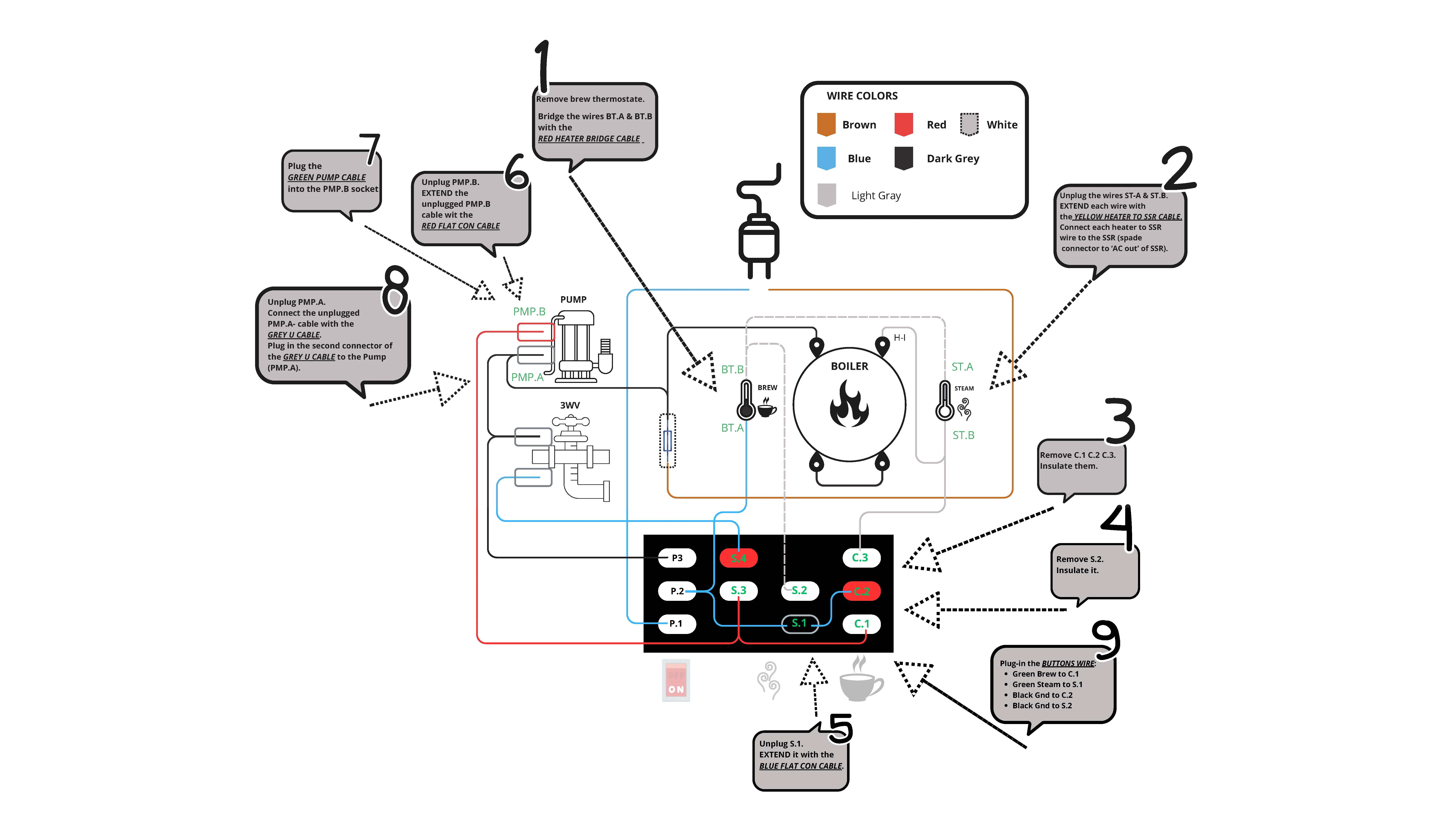
Check the Pinout and prepare the wires if you didn’t buy the kit. We recommend downloading and/or printing the Classic Wiring and Classic Wiring Schematics PDFs. This guide is referencing them.
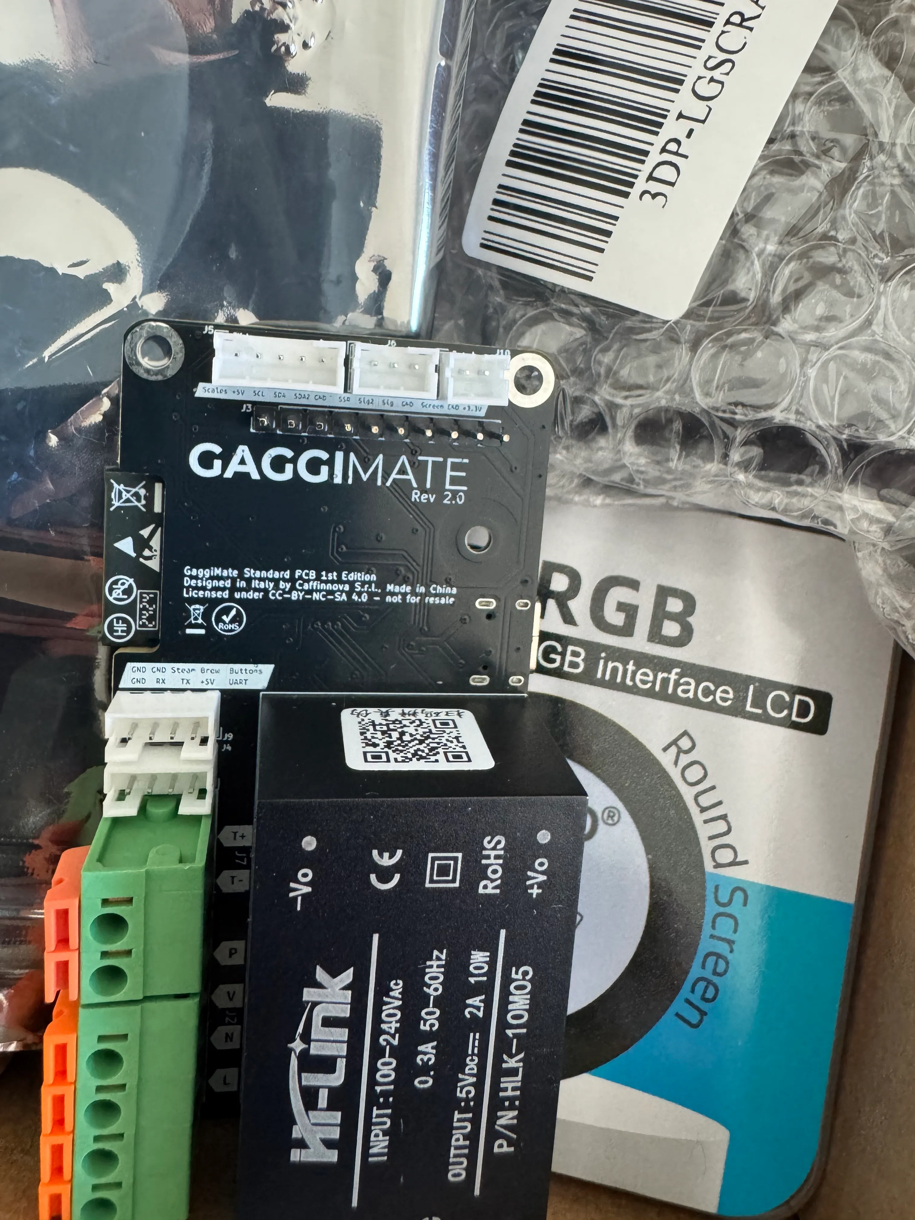
Check all the parts
Check that you have all the parts ready to go. All parts needed are in the full kit (standard or pro).
NOTE: if your machine has faulty parts (switches, pump, solenoid valve, …) the GaggiMate will not magically heal it!
(* that does not apply to blown thermostats, since they will be replaced)
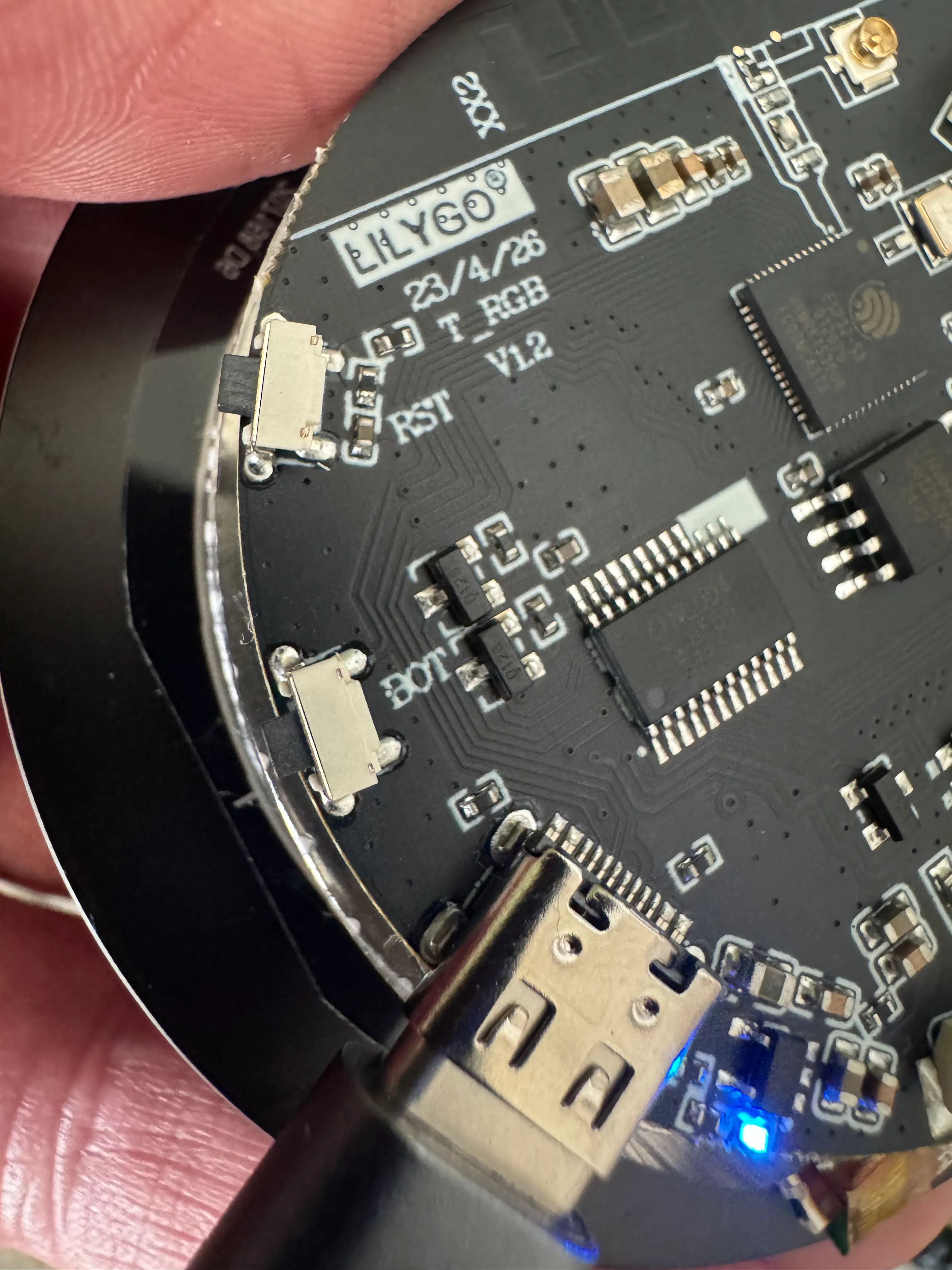
Check the screen
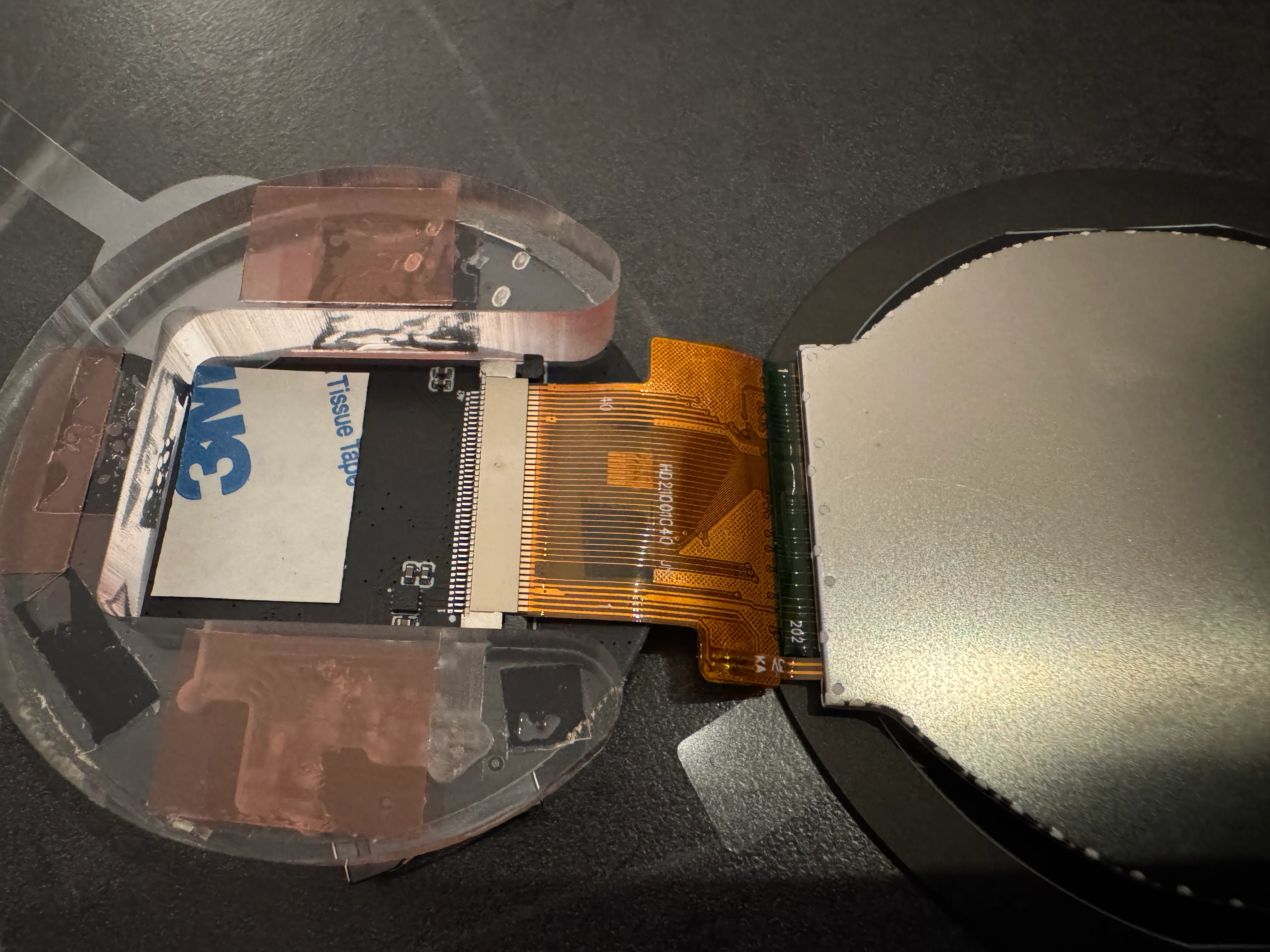
Before you assemble the screen, check that the ribbon is seated and locked correctly like in this picture. If it isn’t for any reason, unlock the connector by pulling down the black locking tab horizontally to the board, insert the cable and close it back up. Check for an image by plugging it into a USB connection before you continue.
Assemble the printed parts
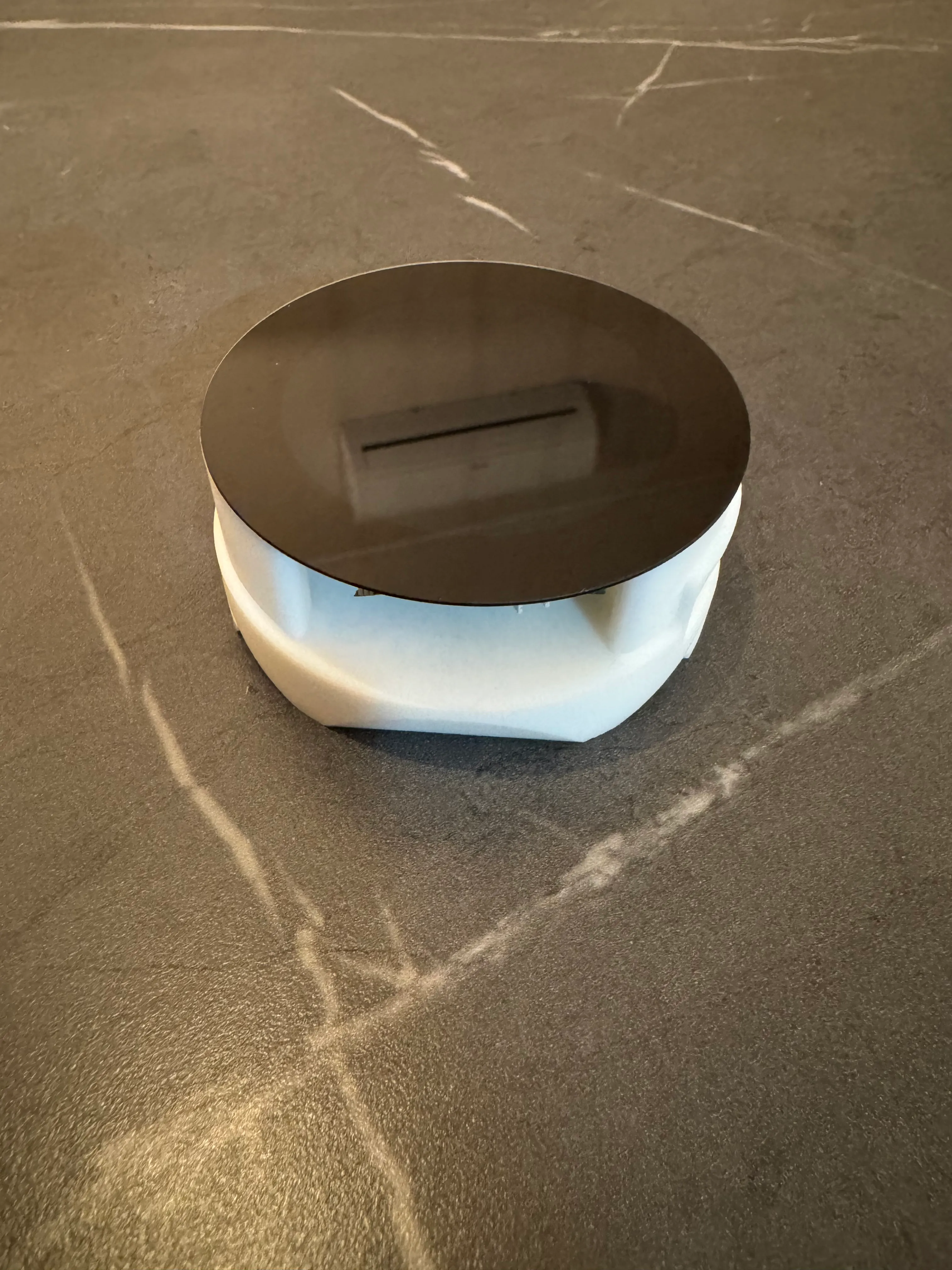
Remove the backing from the adhesive strips on the PCB part and try to stick the screen as straight and centered as possible. Place it in the base and close it gently with the cover. Be careful as the screen may fall apart easily if force is applied. There is no need to remove the plastic piece between in-between the screen and the board.
Place the PCB in the pcb cover at an angle to guide the USB-C port in the cutout. Afterwards push it down to lock it in the base. Make sure you’ve already flashed it before as you might need to access the boot button to do so.
Machine preparation
Disassemble the machine
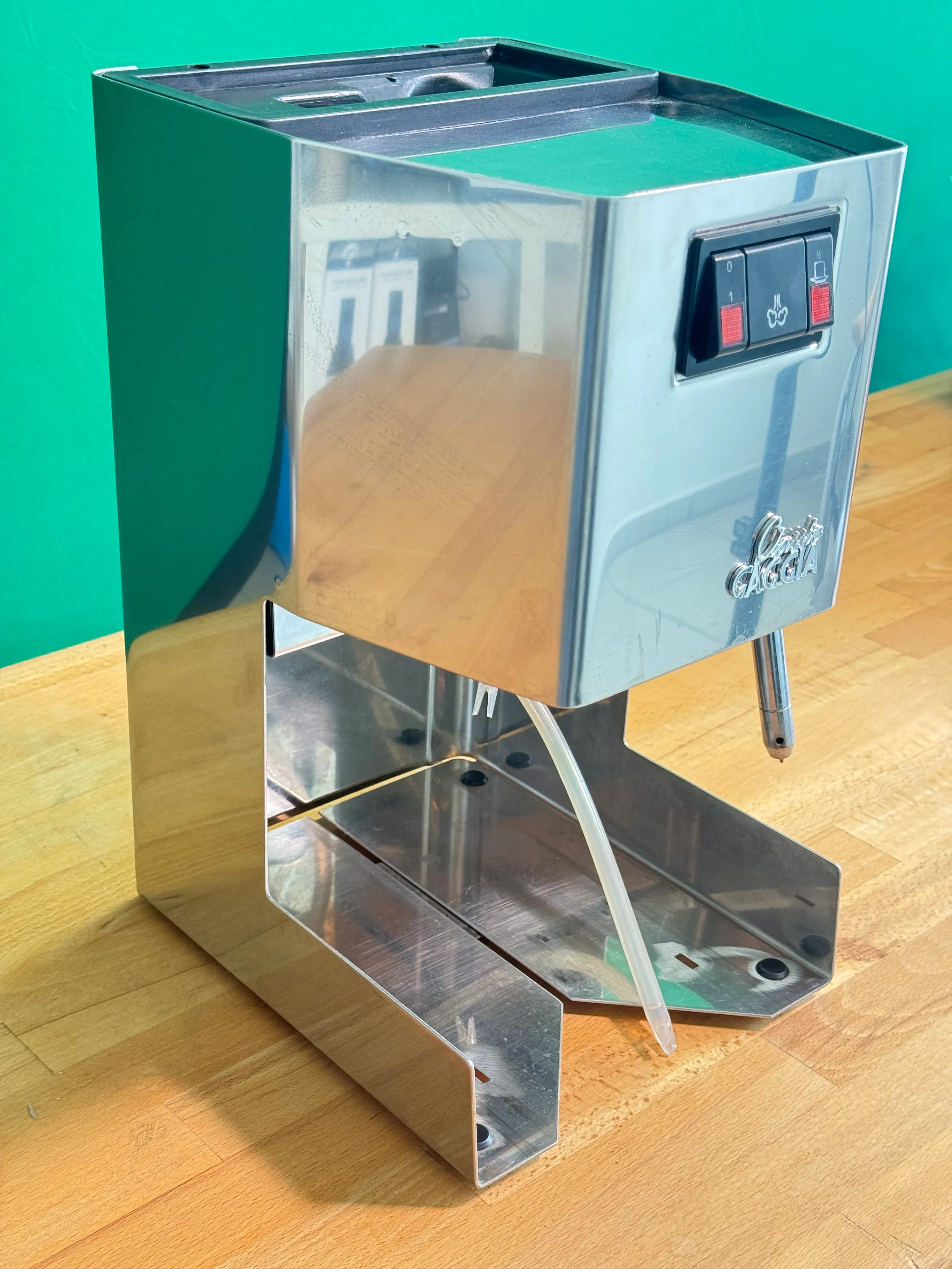
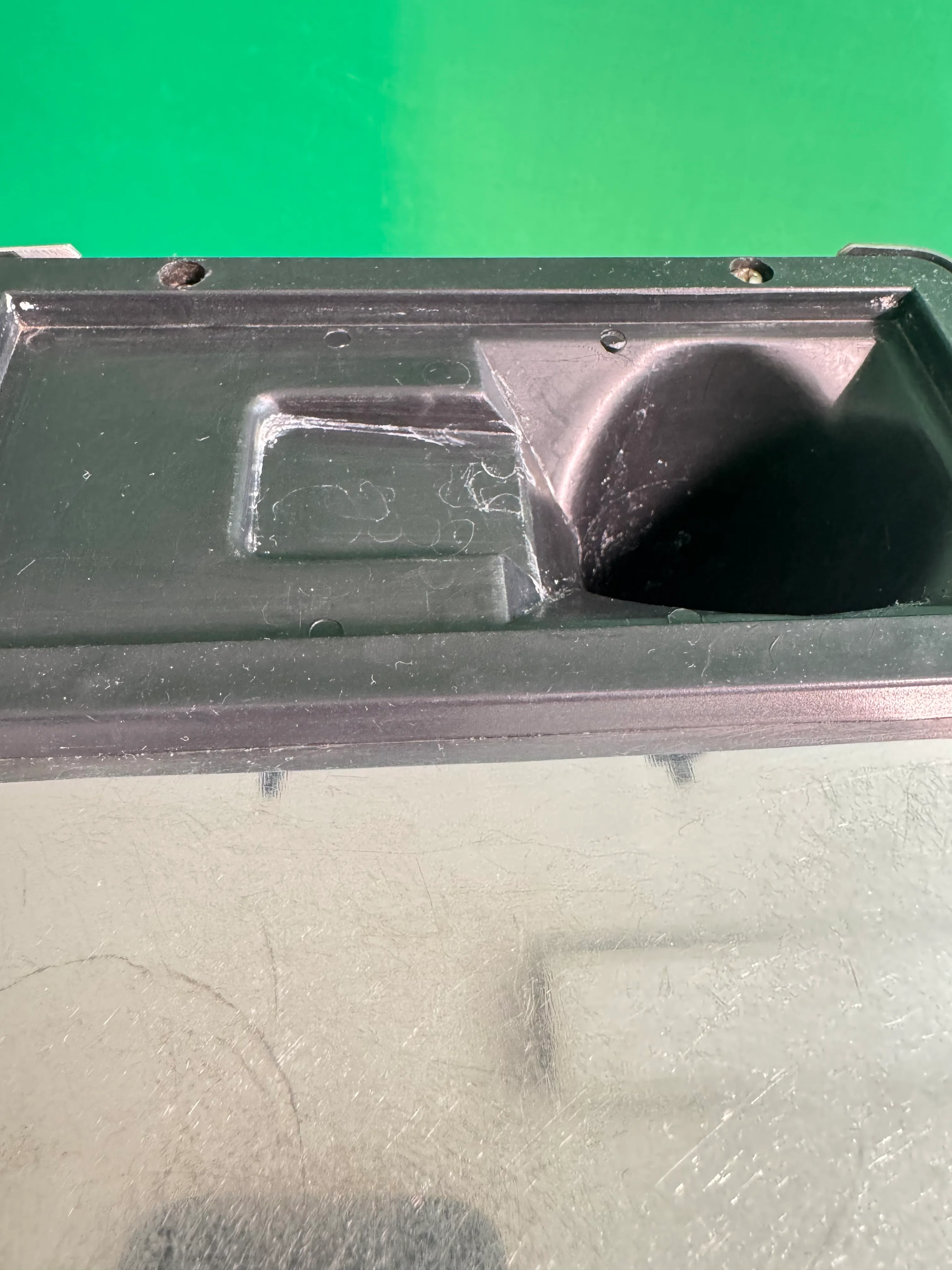
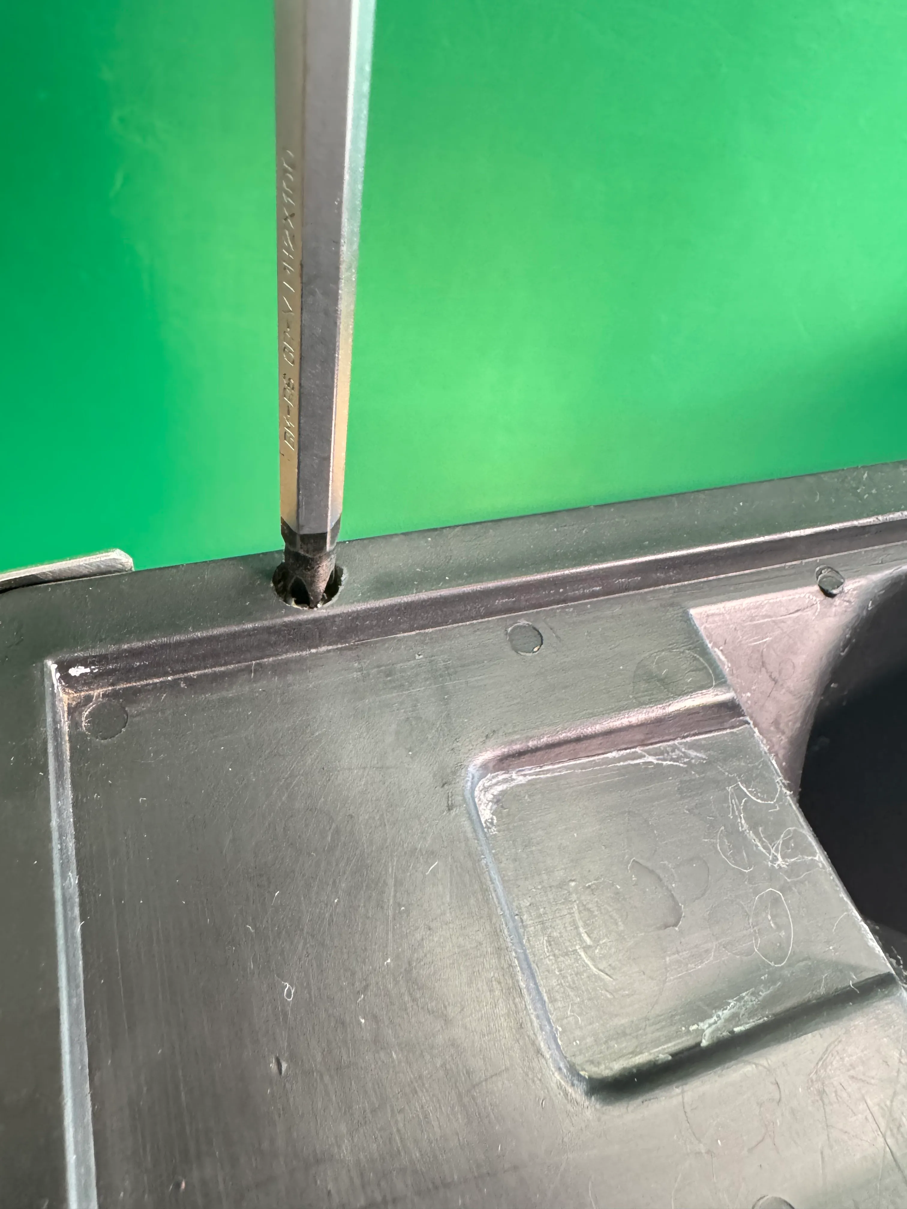
Remove all parts from the machine that could bother you during the installation or fall out like the water lid, drip tray and portafilter. Remove the two screws marked above in the picture.
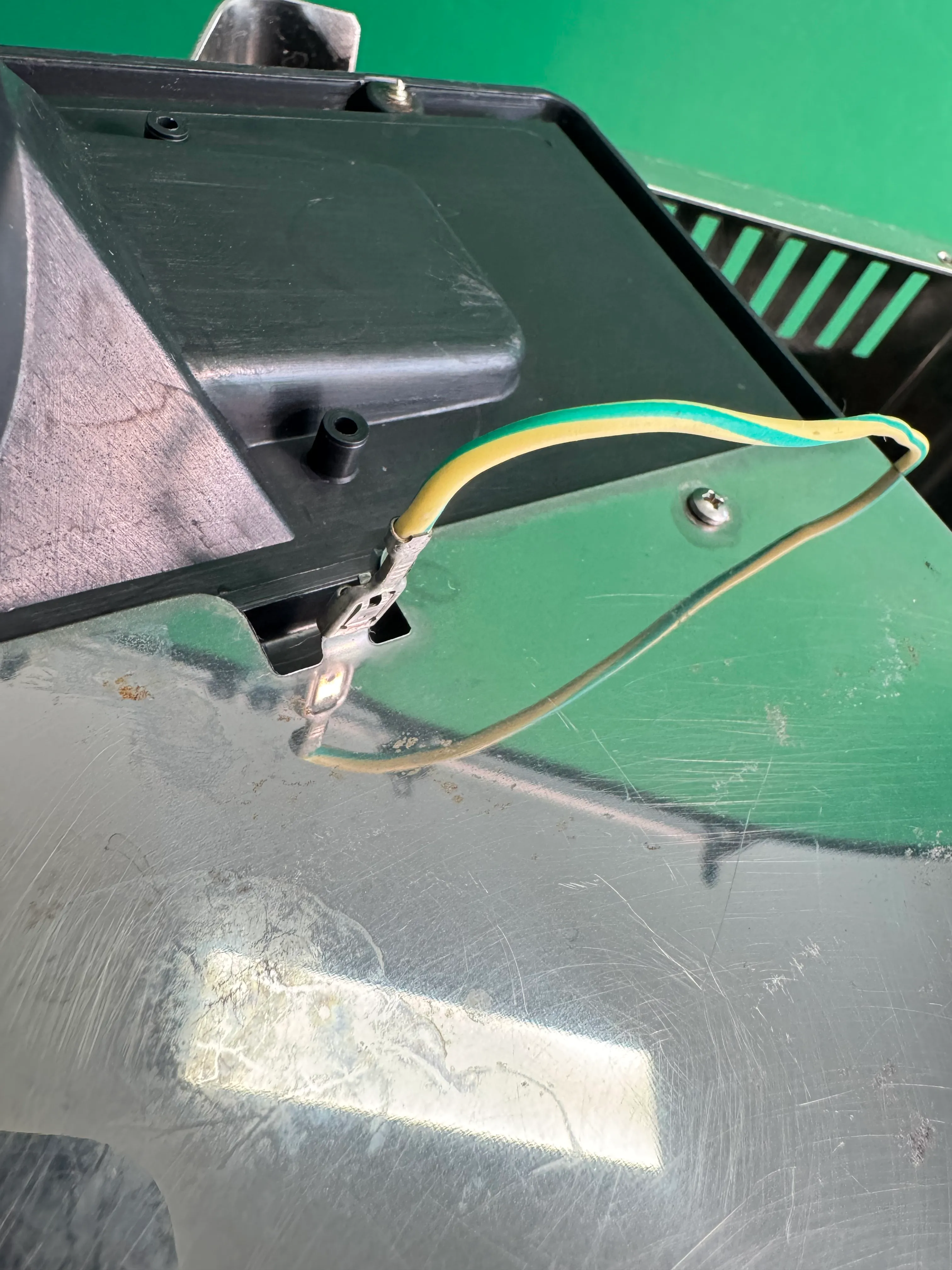
This allows you to remove the cupwarmer. Unplug the grounding wire on the flip side of the warmer. Remember to connect it again when re-assembling!
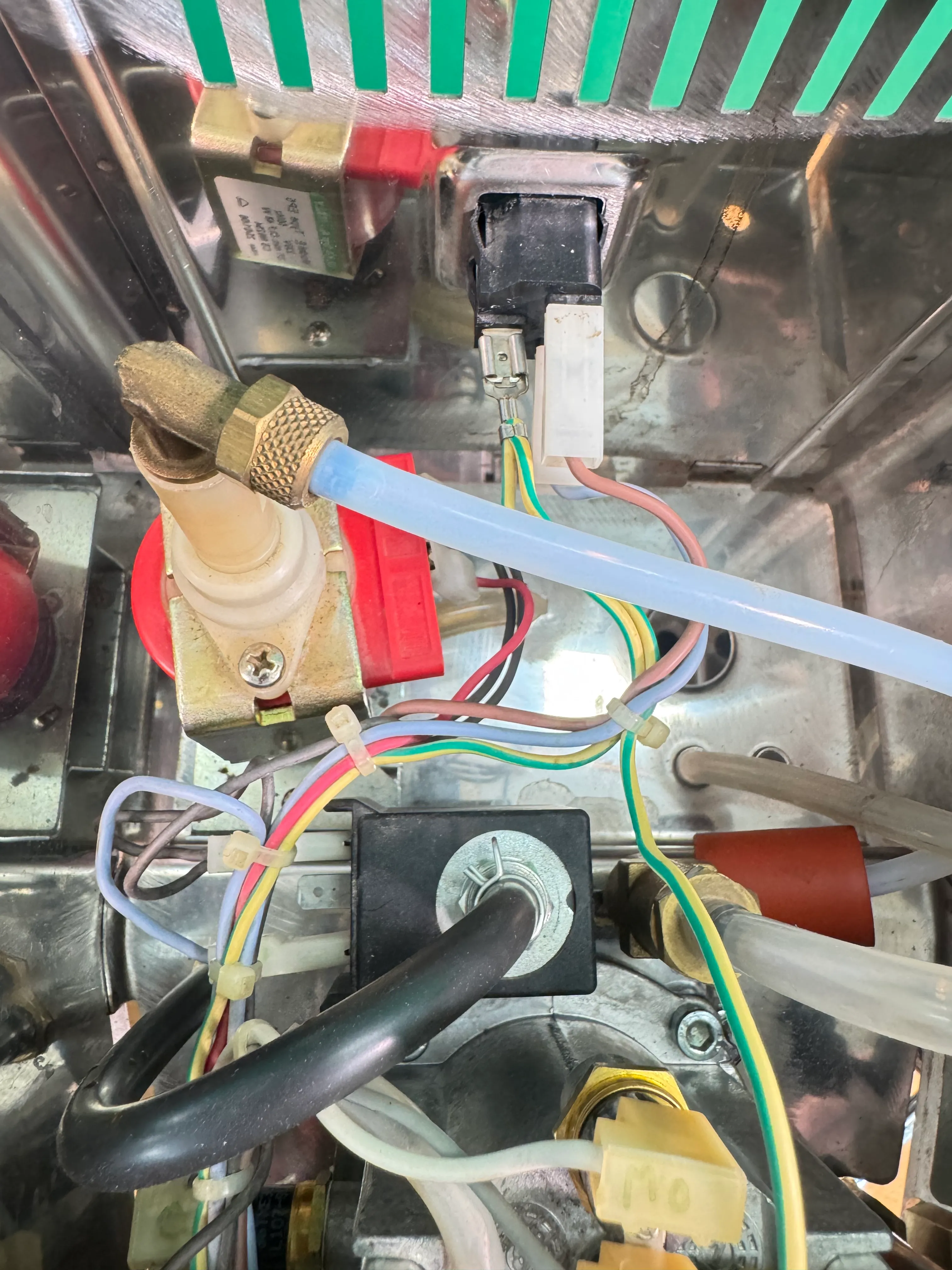
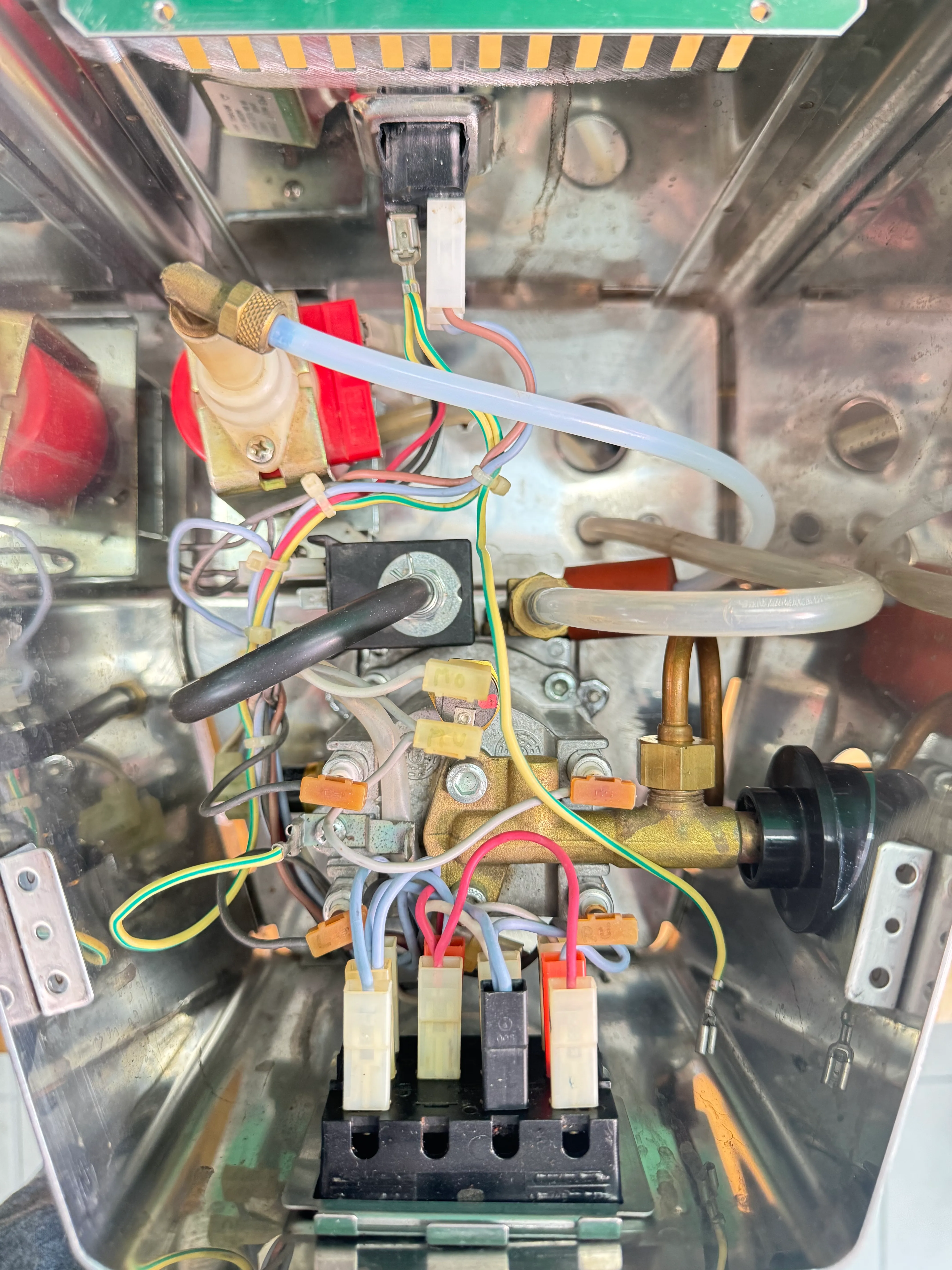
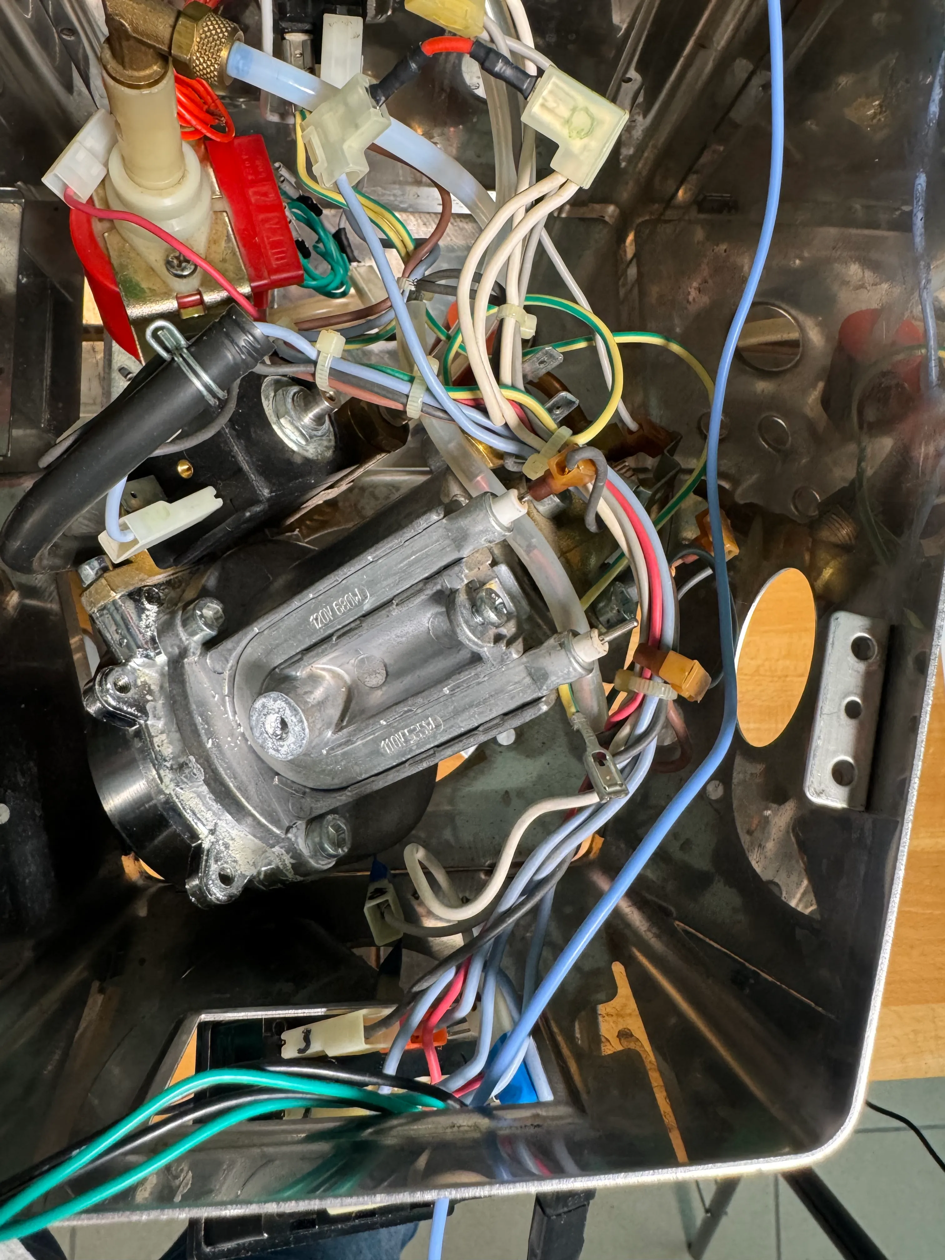
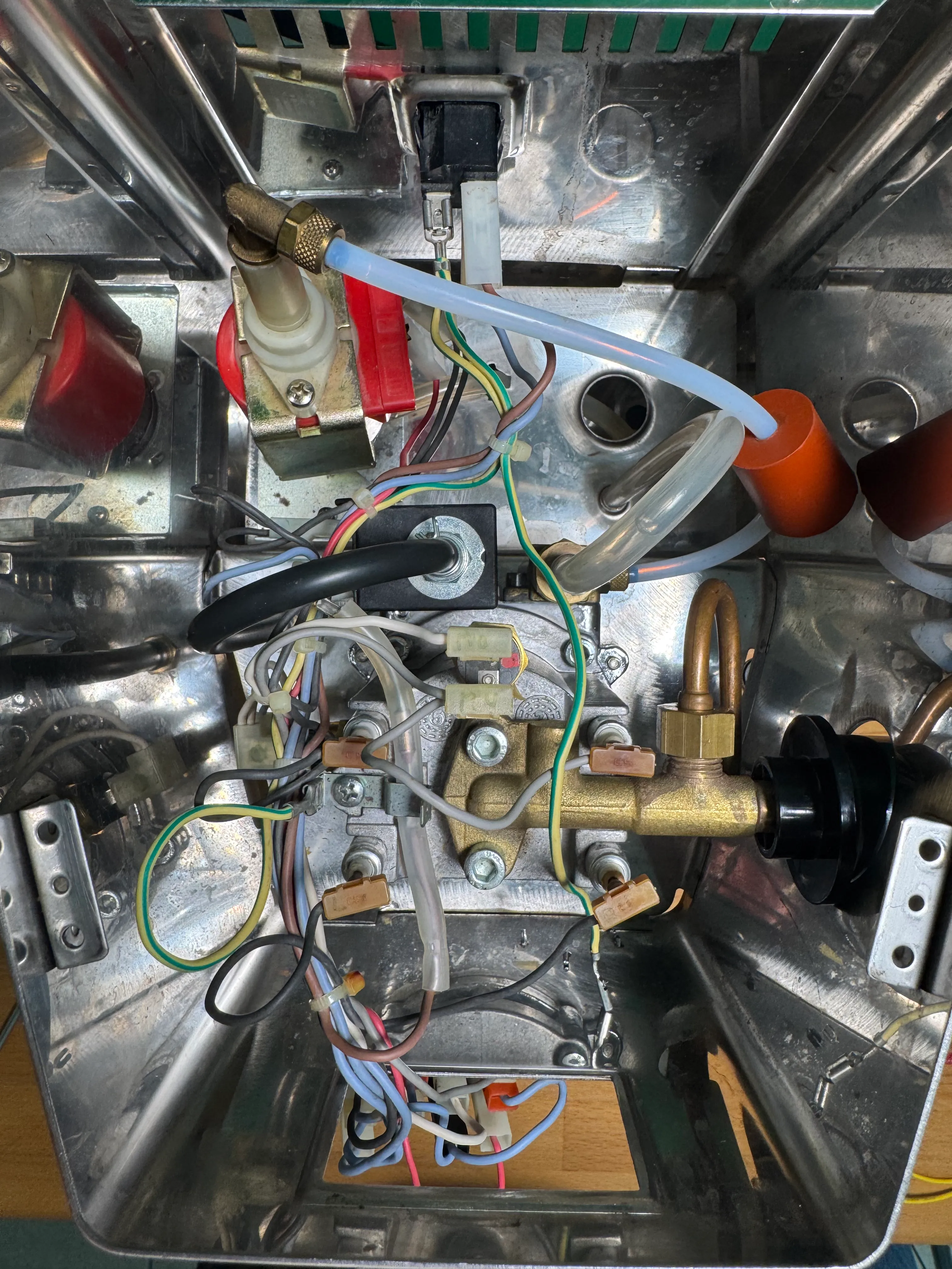
Make yourself familiar with the guts of the machine. Remember: we are working on a Gaggia Classic (NOT Gaggia Classic Pro / E24 / Evo).
Making room by moving the switches
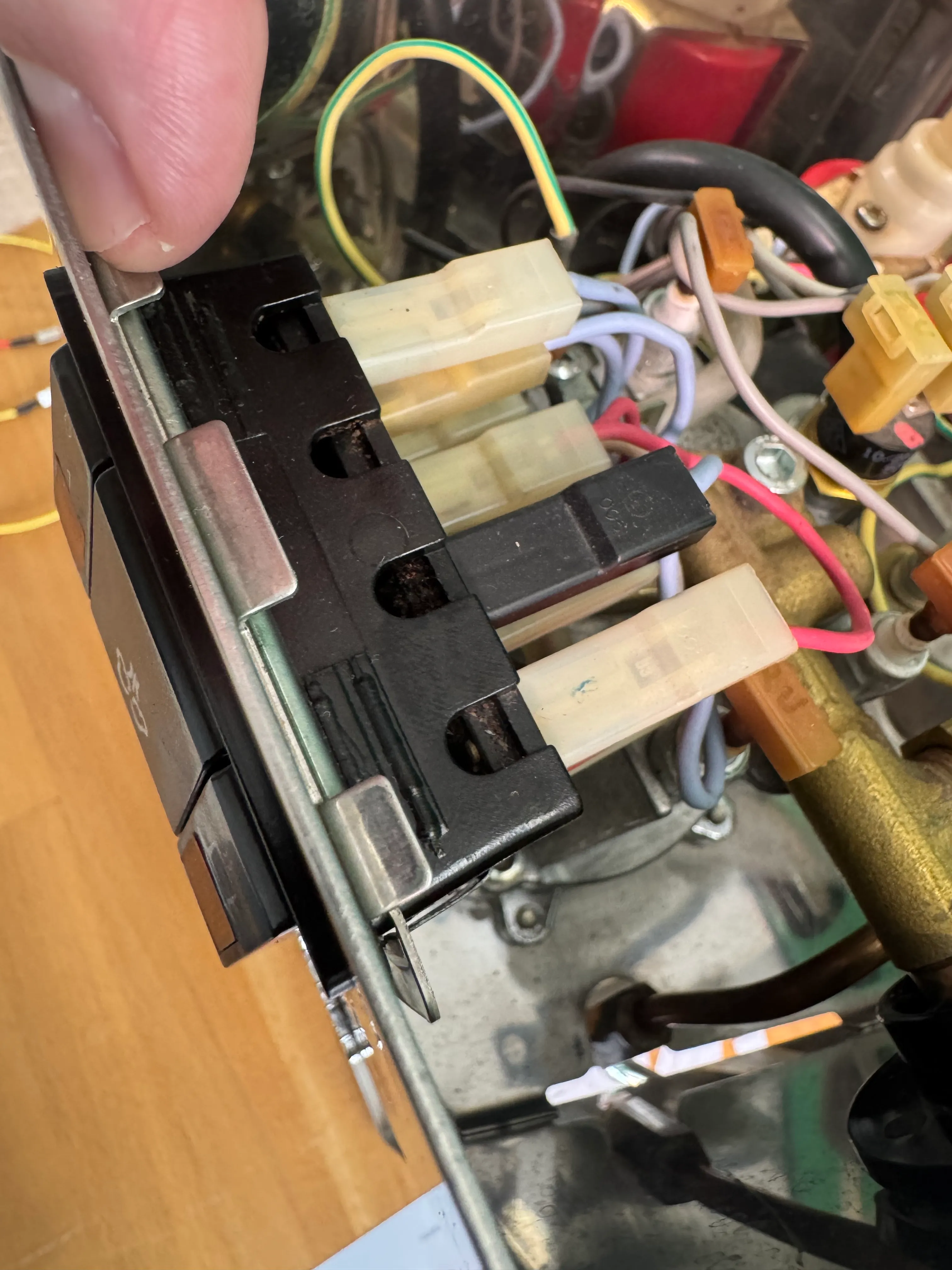
Pry the rectangular clamp around the switches open and move it a little towards the inside of the machine. We will remove it later.
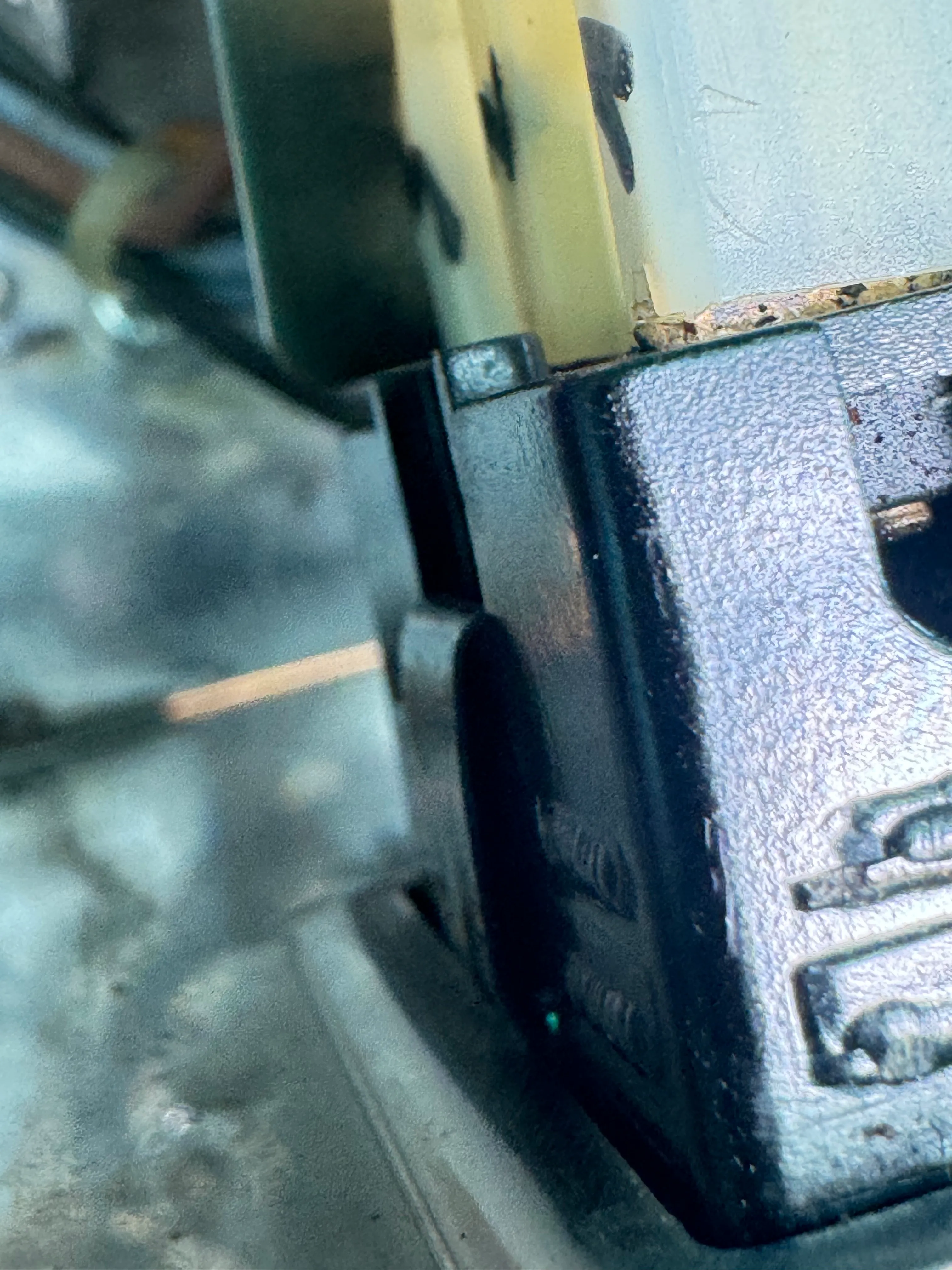
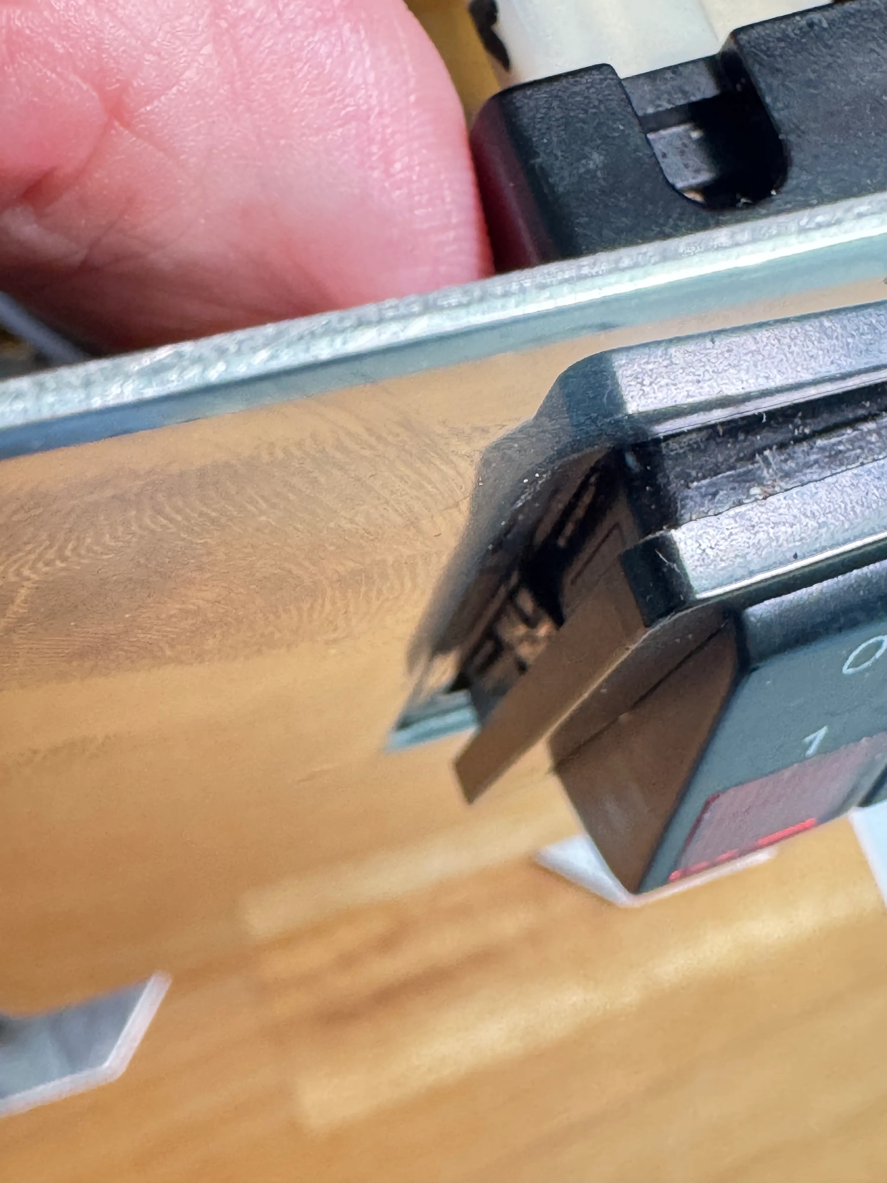
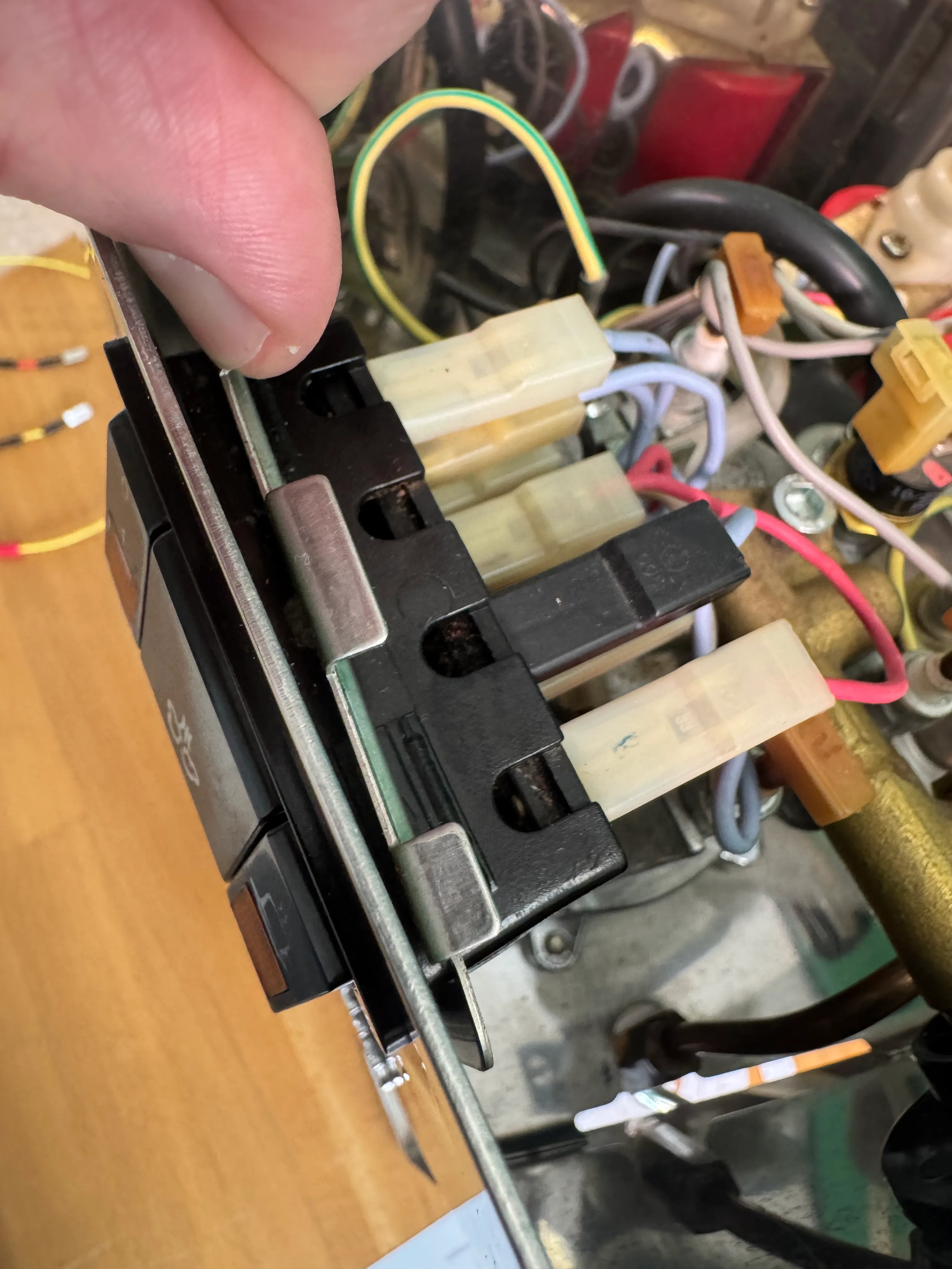
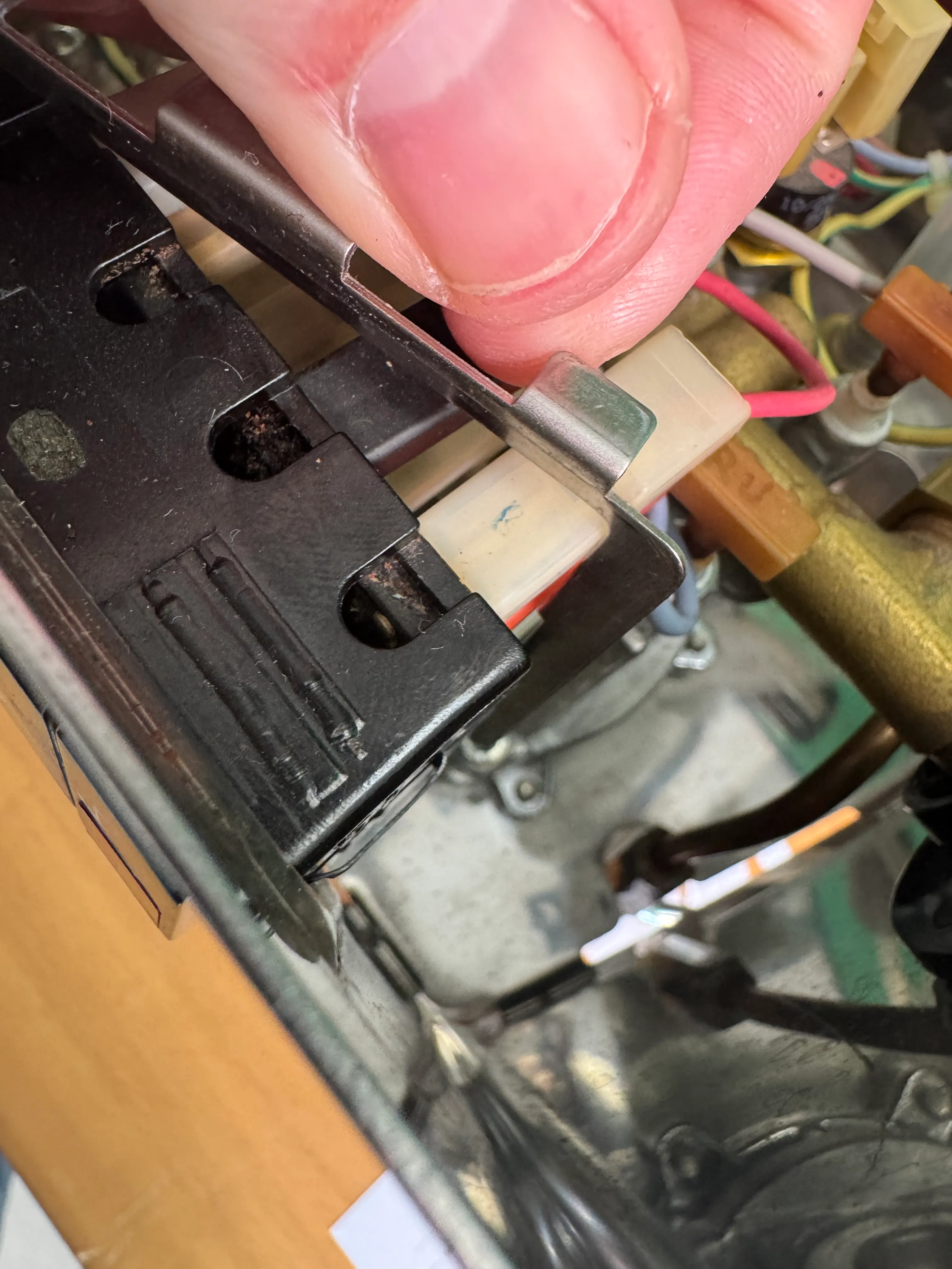
Find the flat metal spring on both sides of the switches section that hold it in place. Squeeze it and then move the whole section out of the housing. It is easier if you work on one side first and then move to the other.
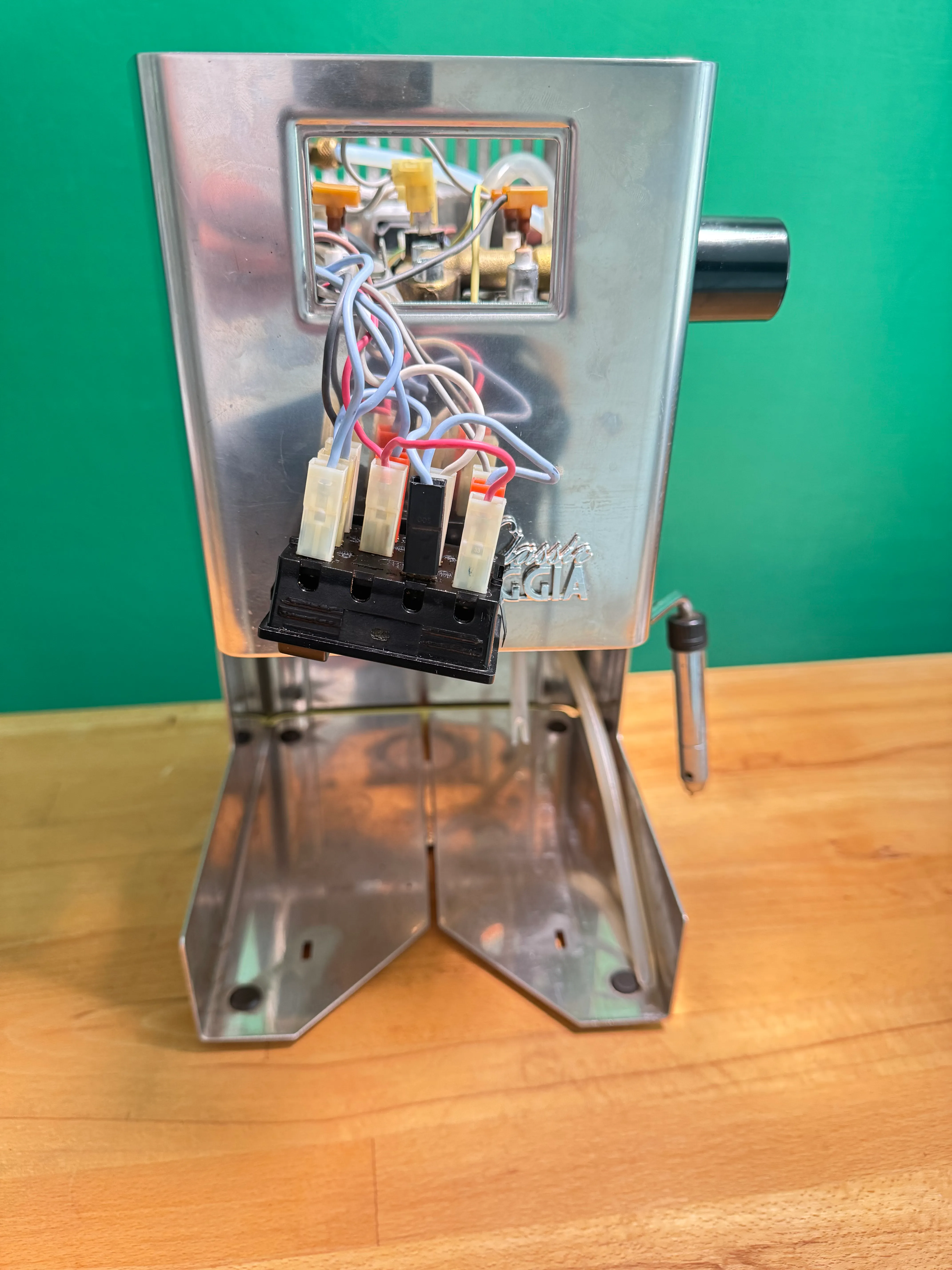
Now you can easily remove the clamp. It is cut on the bottom so you can lead the wires through. Tilt the switches section as shown above.
Compare your stock wiring with the Classic Wiring Schematics. In case something, i.e. your wire coloring, differs from the PDF, you should be able to understand and adapt the guide to your individual machine.
The next steps will follow steps 1 through 9 of the PDF.
OPTIONAL / RECOMMENDED
We recommend making more room in order to more easily access the parts and wires:
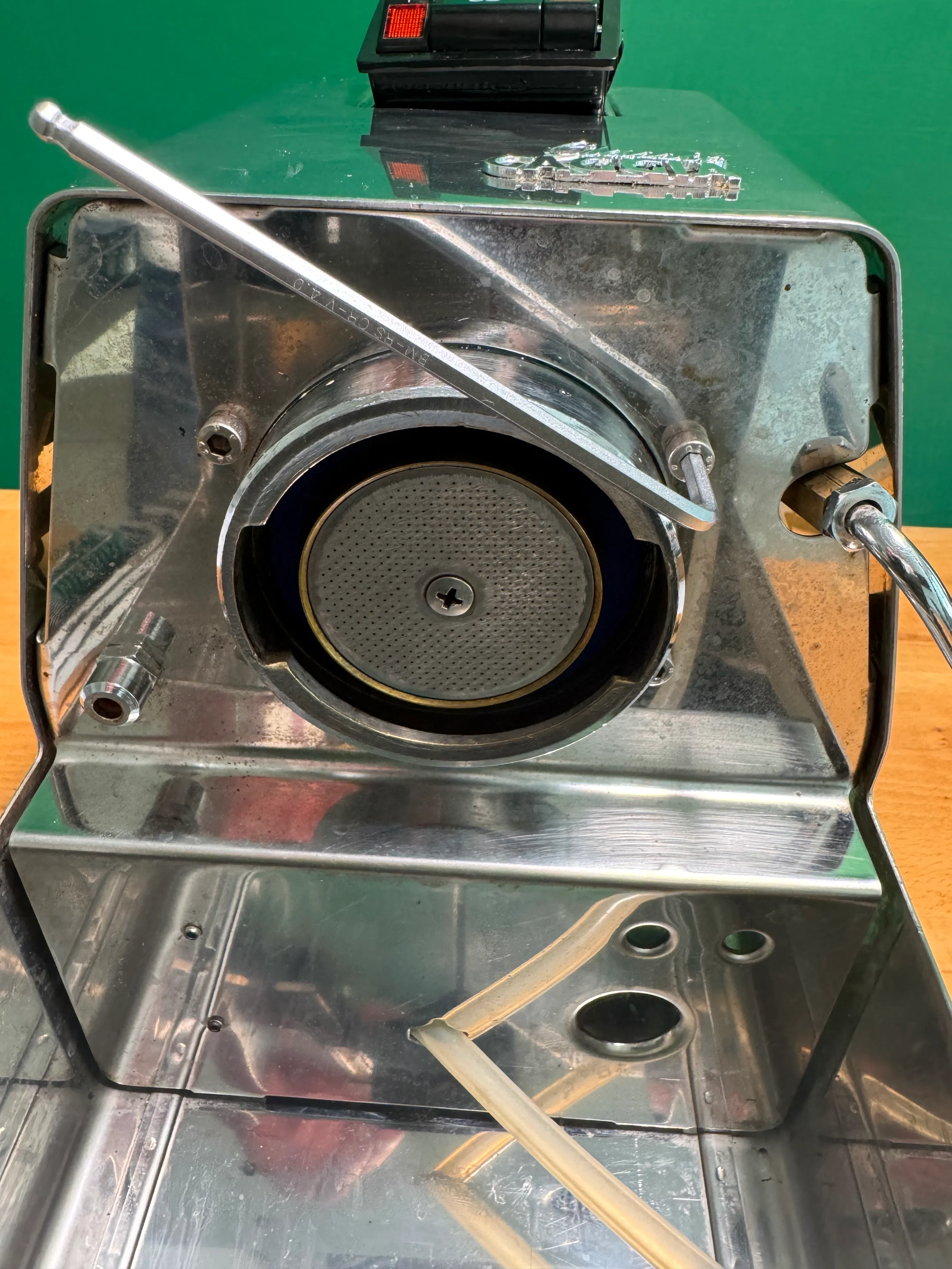
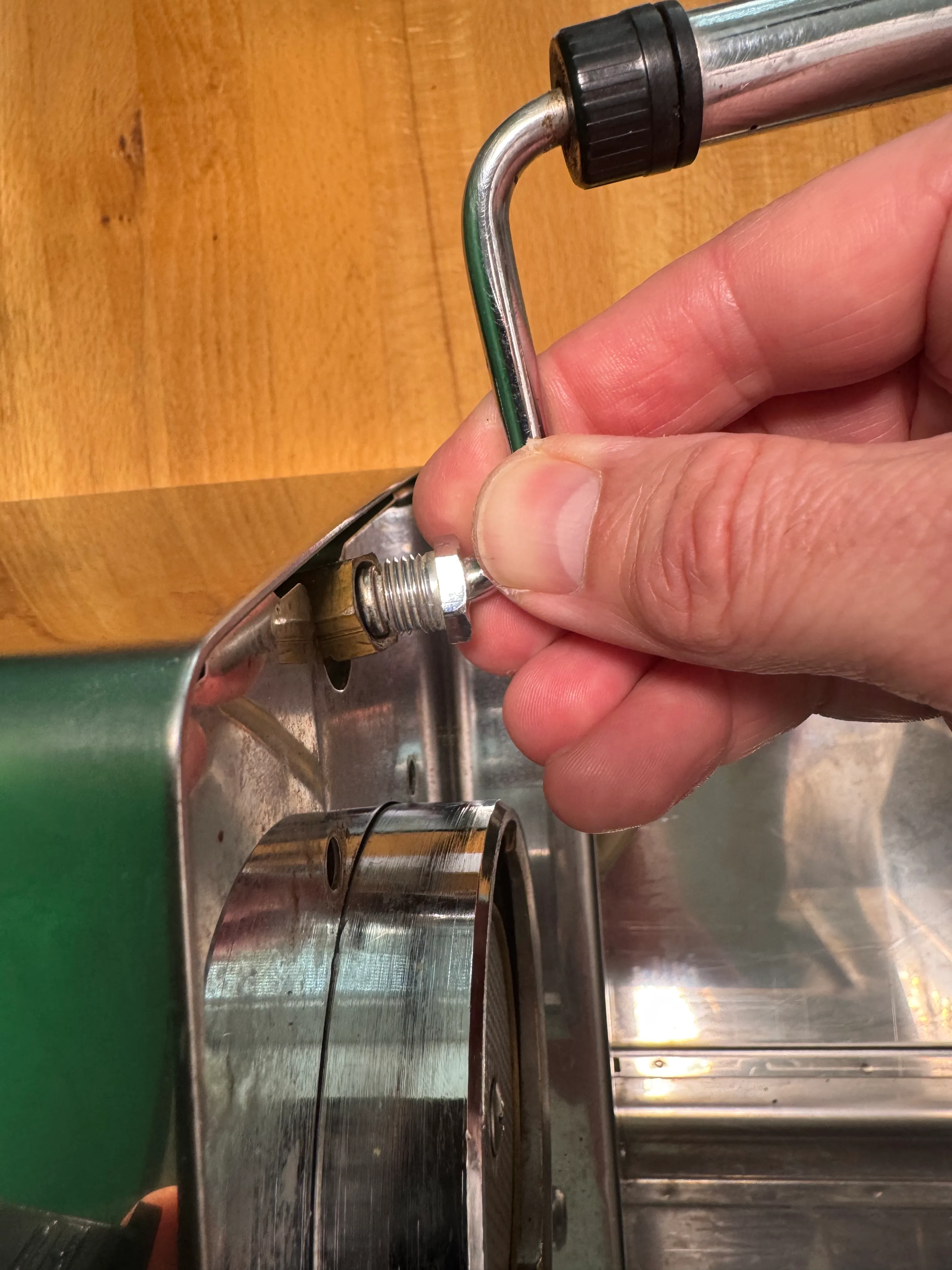
- With an allen key: unscrew the 4 screws that hold the boiler
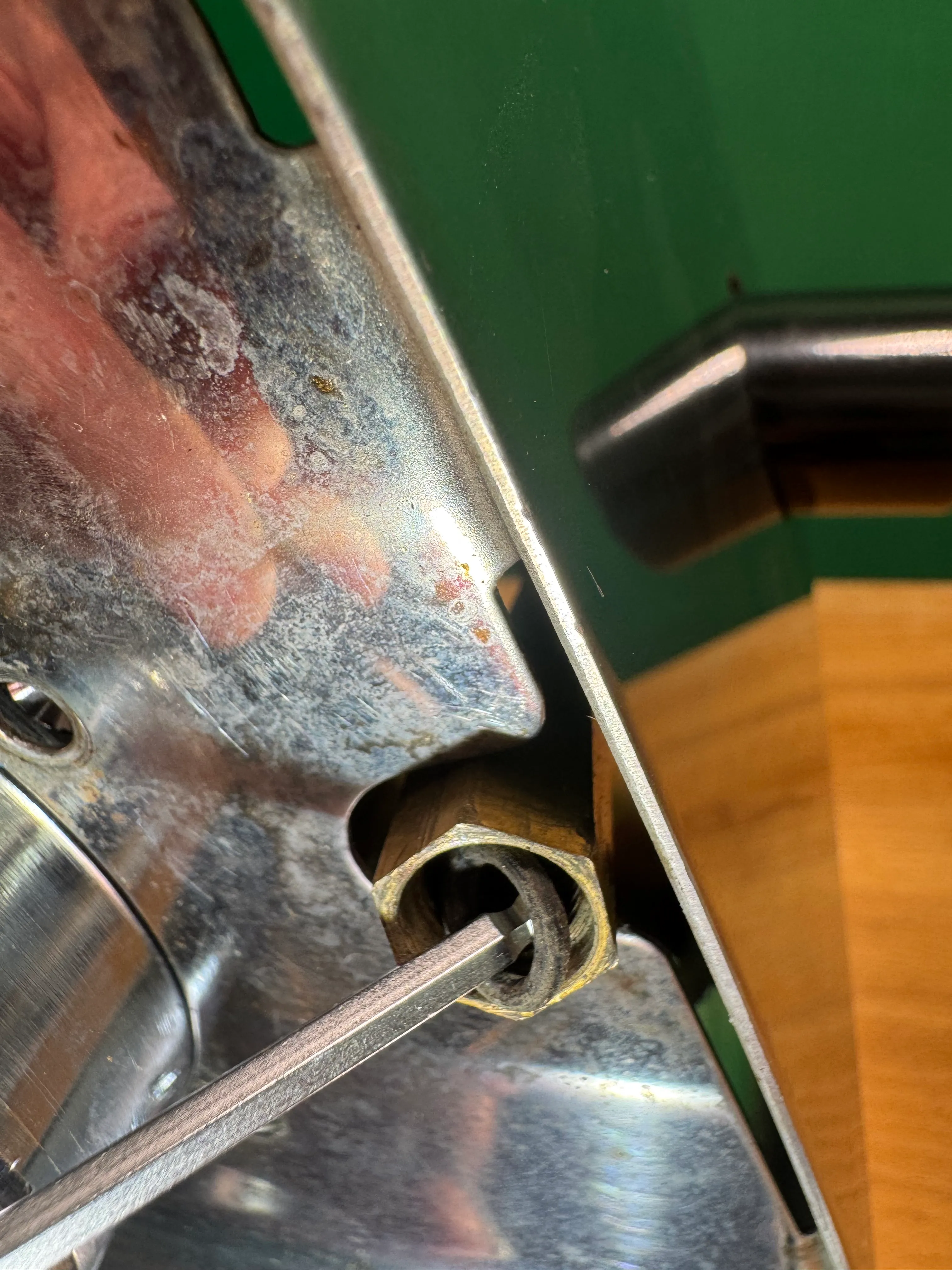
- Unscrew and remove the steam wand
- Do not forget the gasket
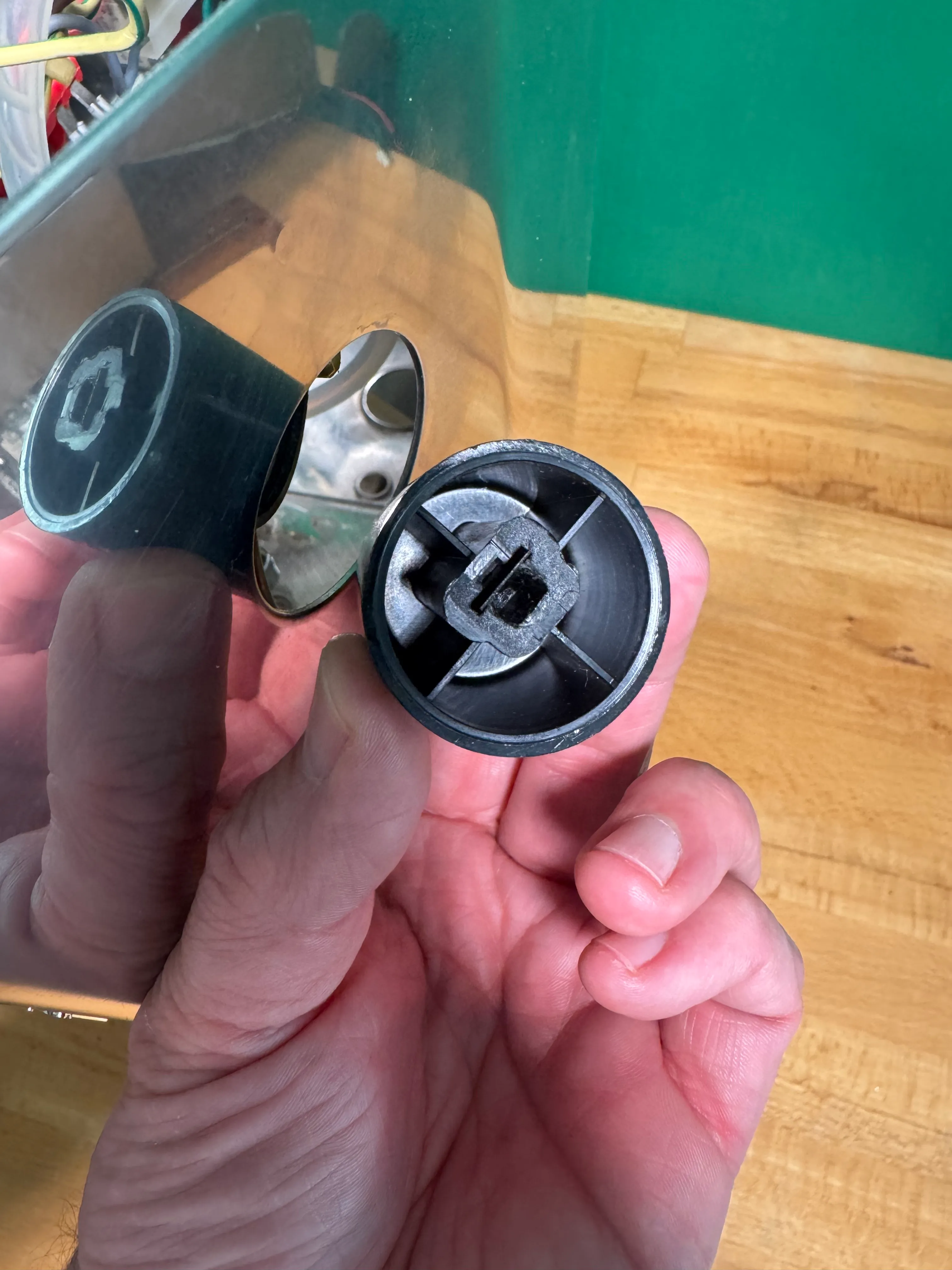

- Remove the steam knob by pulling it firmly. Make sure you do not lose the metal spring inside the knob.
- Remove the heat protection disc by also pulling it off.
Optional: This gives you more space for the installation.
- Find the black overpressure hose on the 3-way solenoid.
- Use pliers to loosen the clamp and move it up the hose.
- Remove the hose from the solenoid.
Heater modifications
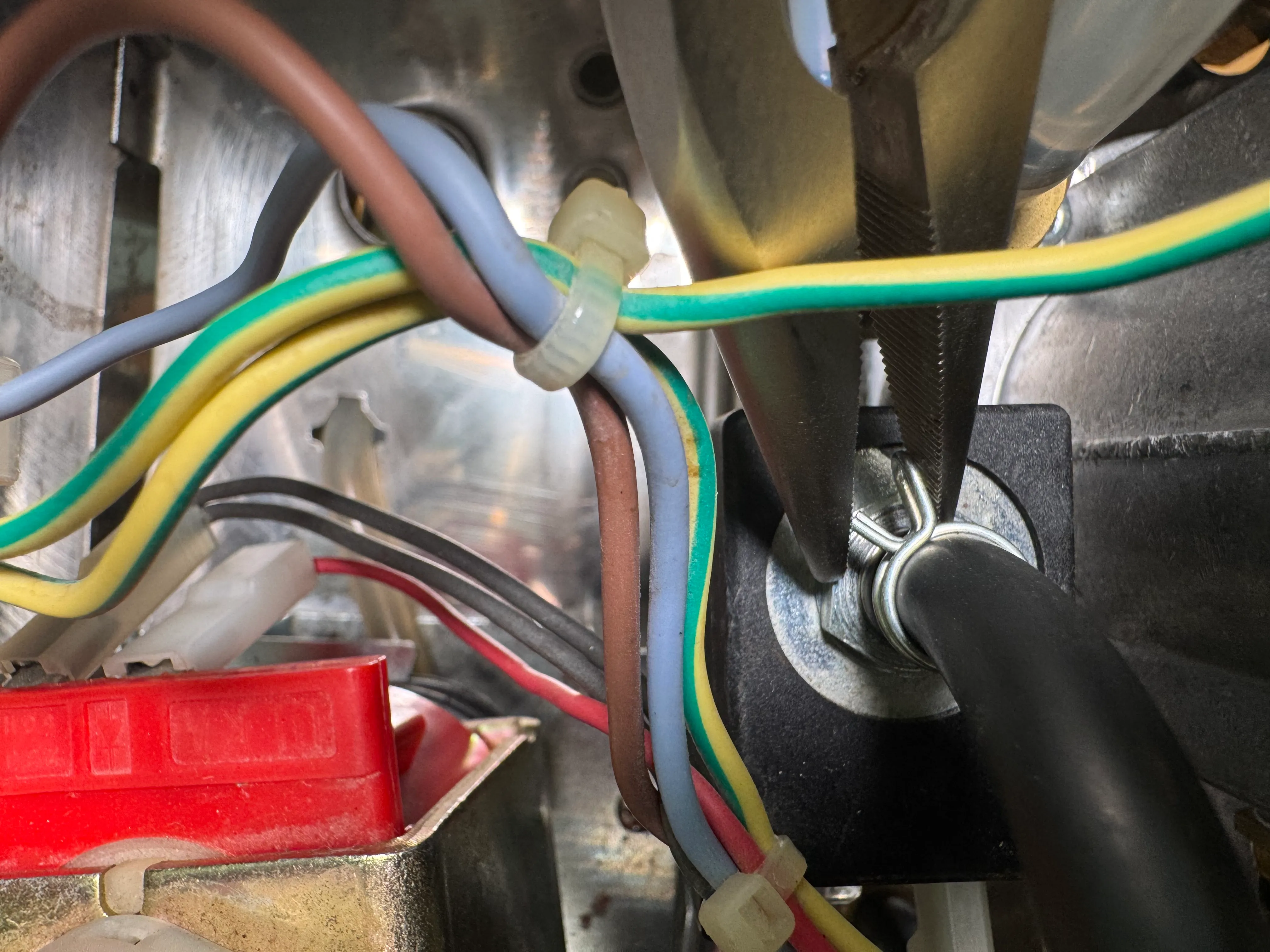
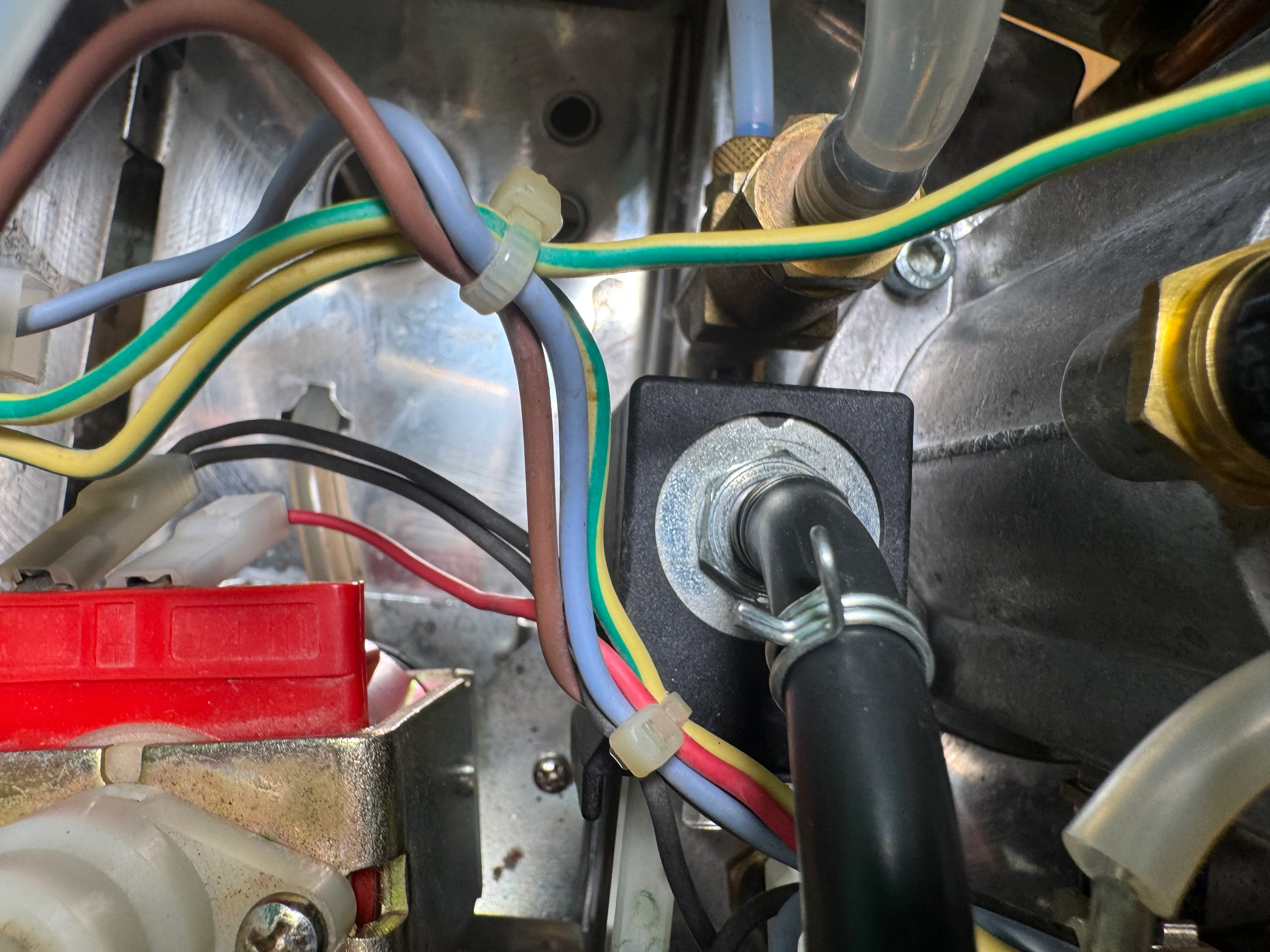
1 Brew thermostat
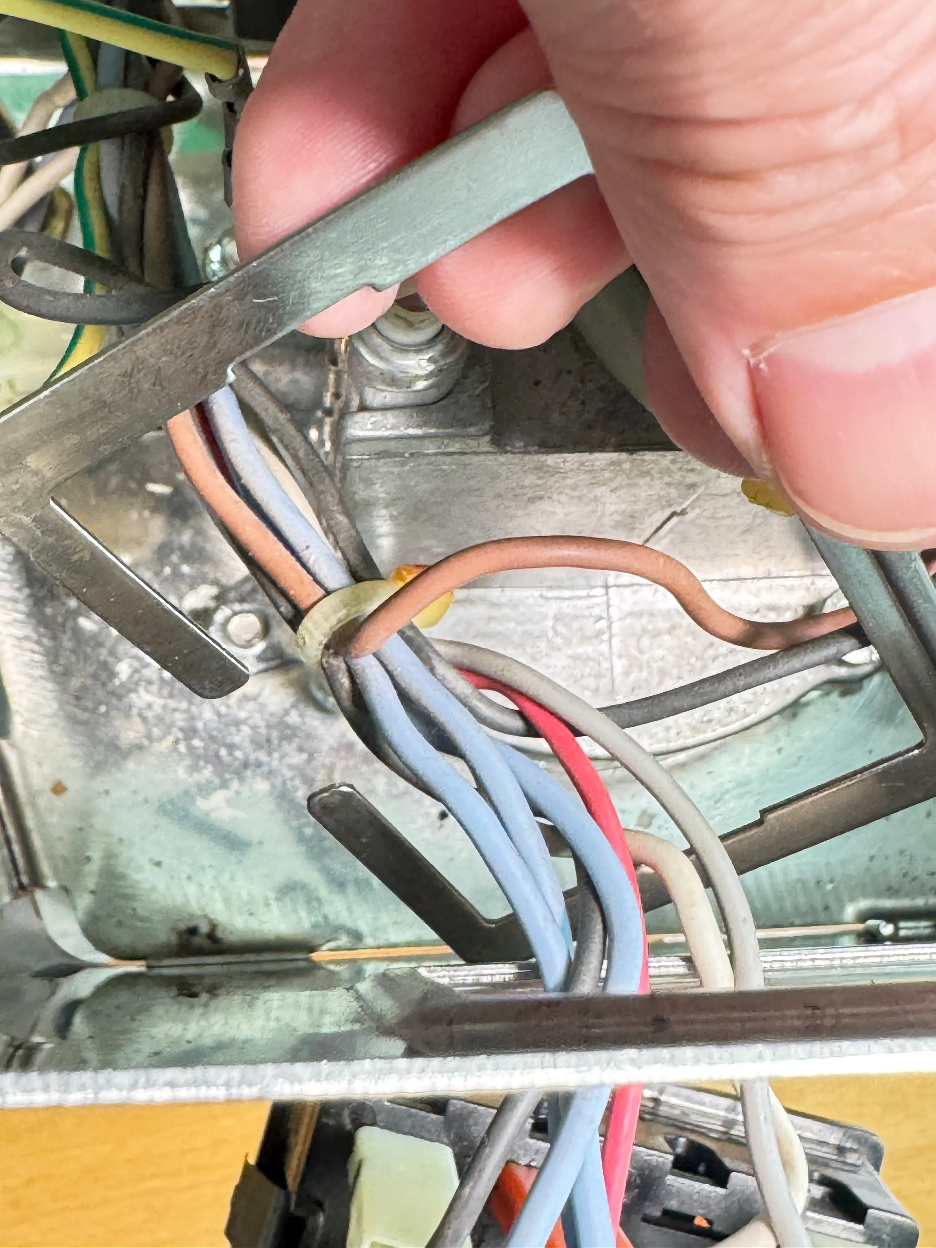
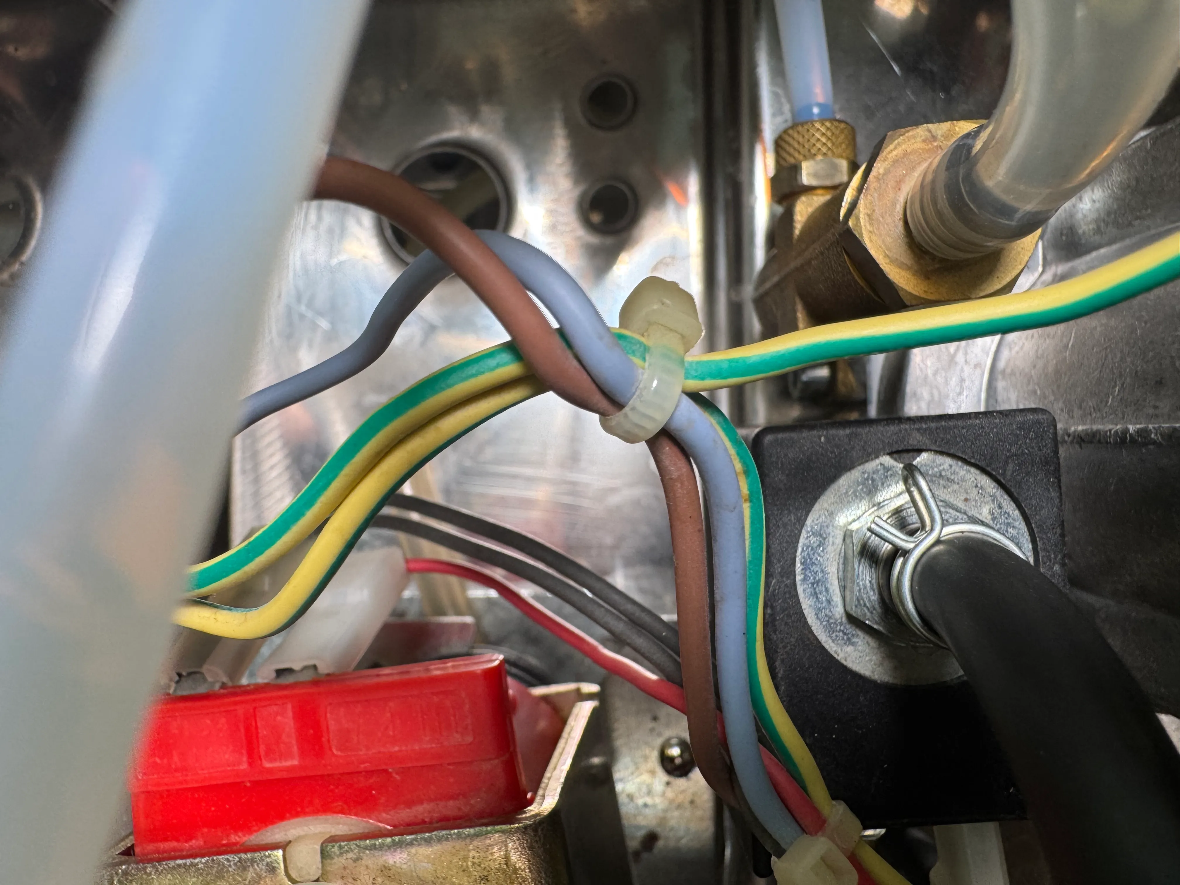
Free the clamp that is also holding the grounding wire.
Find the brew thermostat at the boiler; it is the one on the SIDE. Unplug the wires BT.A and BT.B.
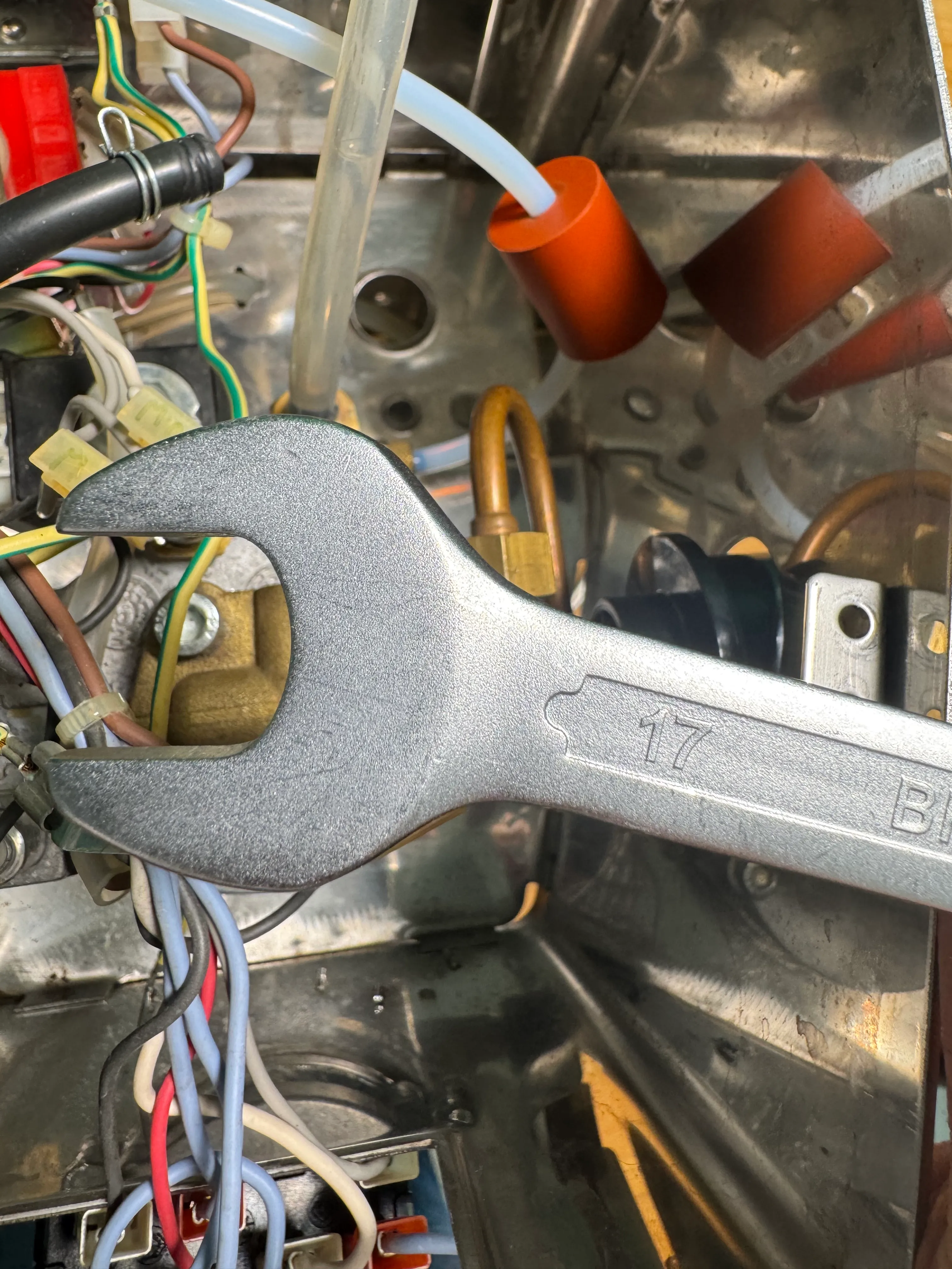
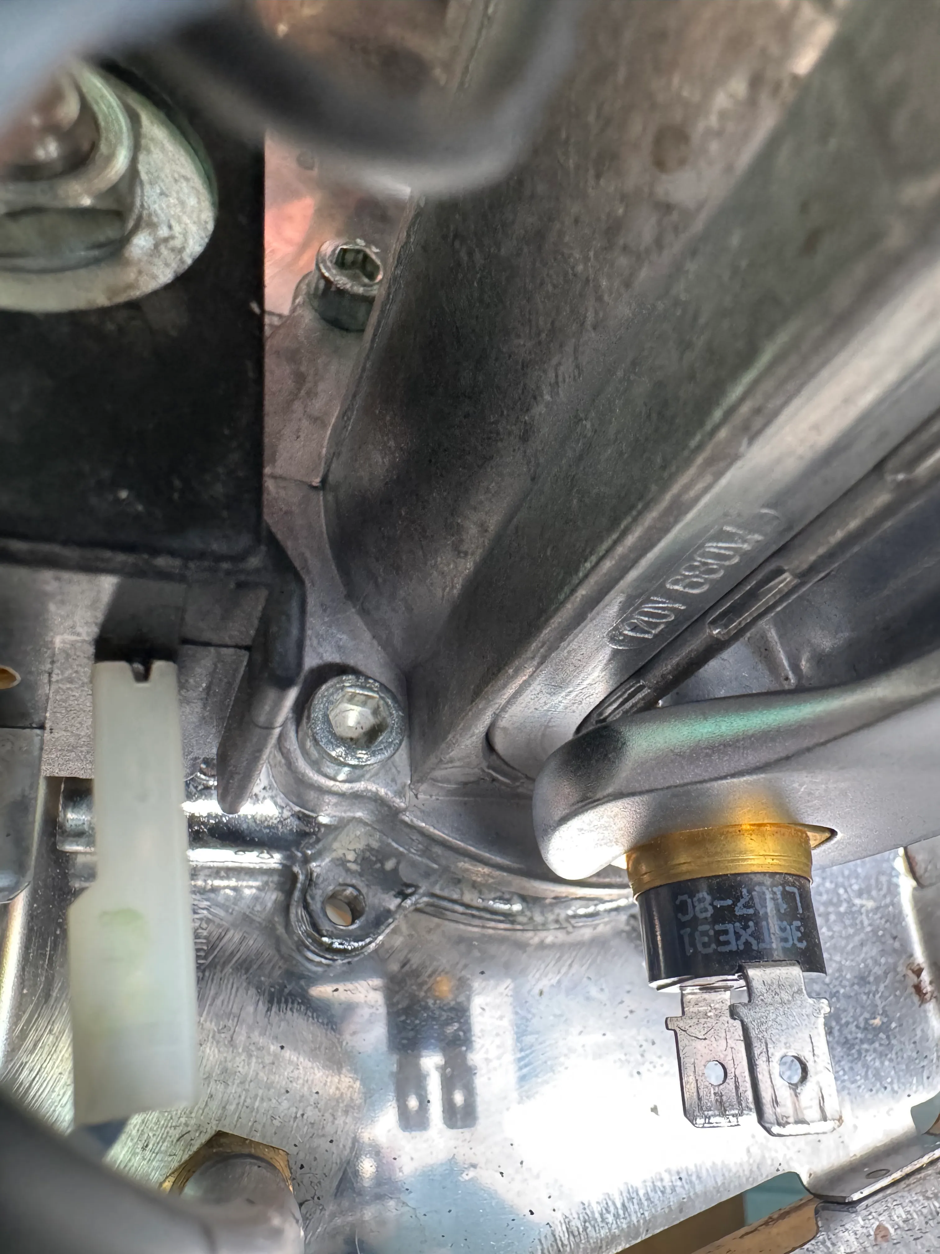
Since you can now easily tilt and shift the boiler, unscrew the thermostat with a 17mm wrench. Put it aside- it is not needed anymore. Bridge the 2 wires BT.A and BT.B. with the red Heater bridge cable.
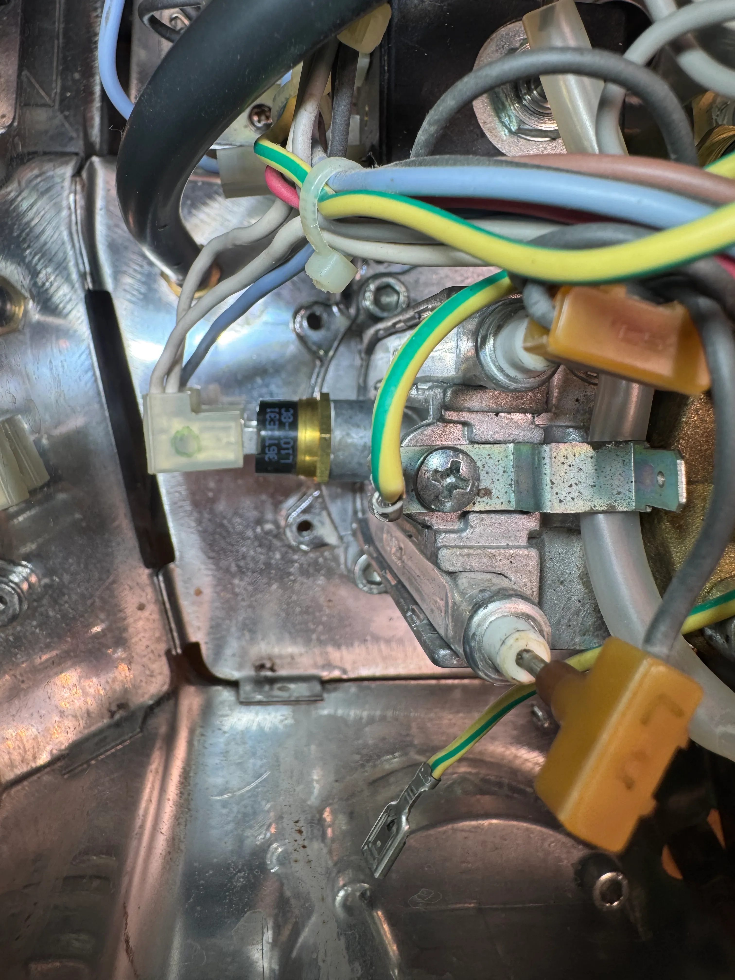
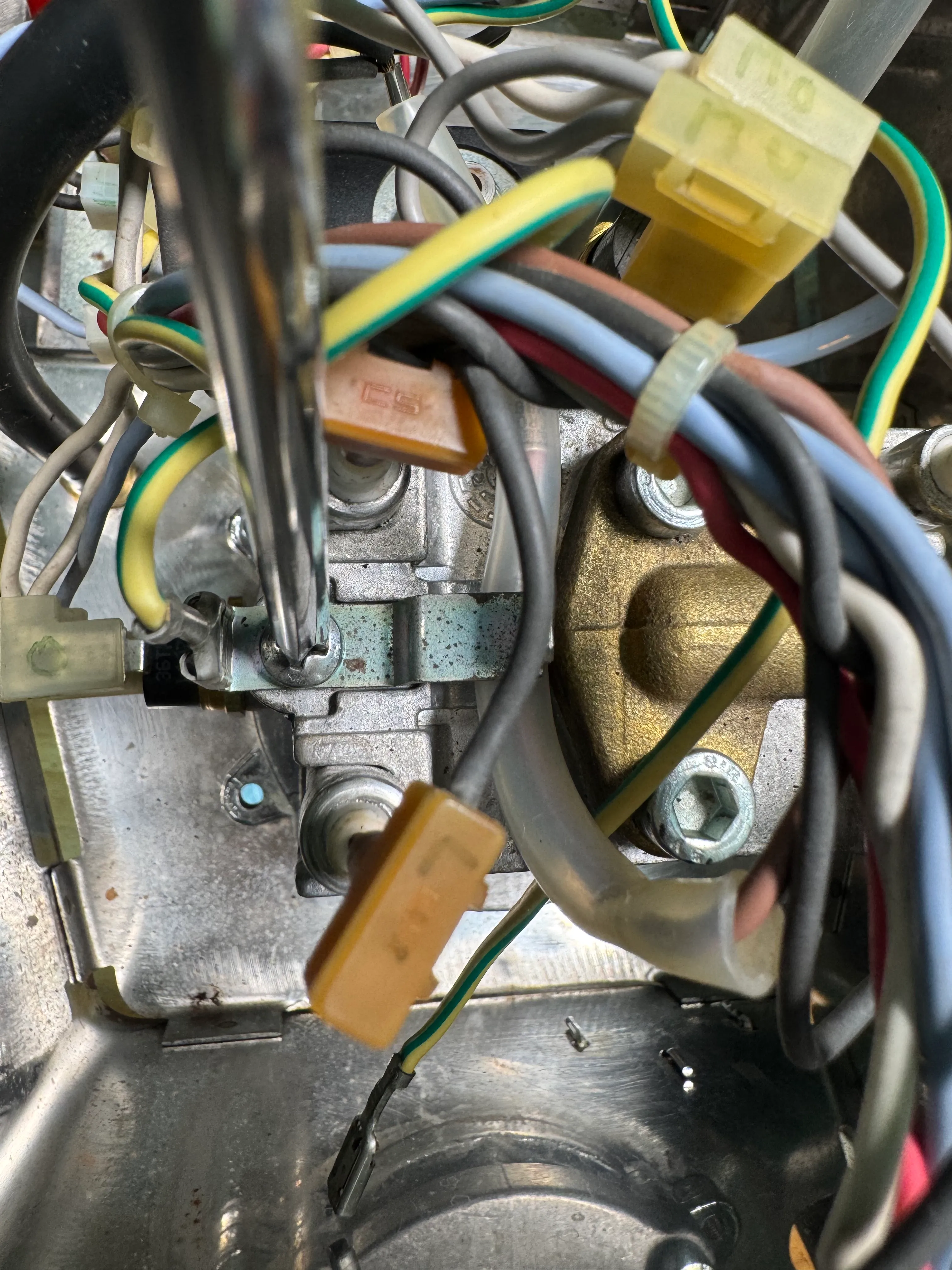
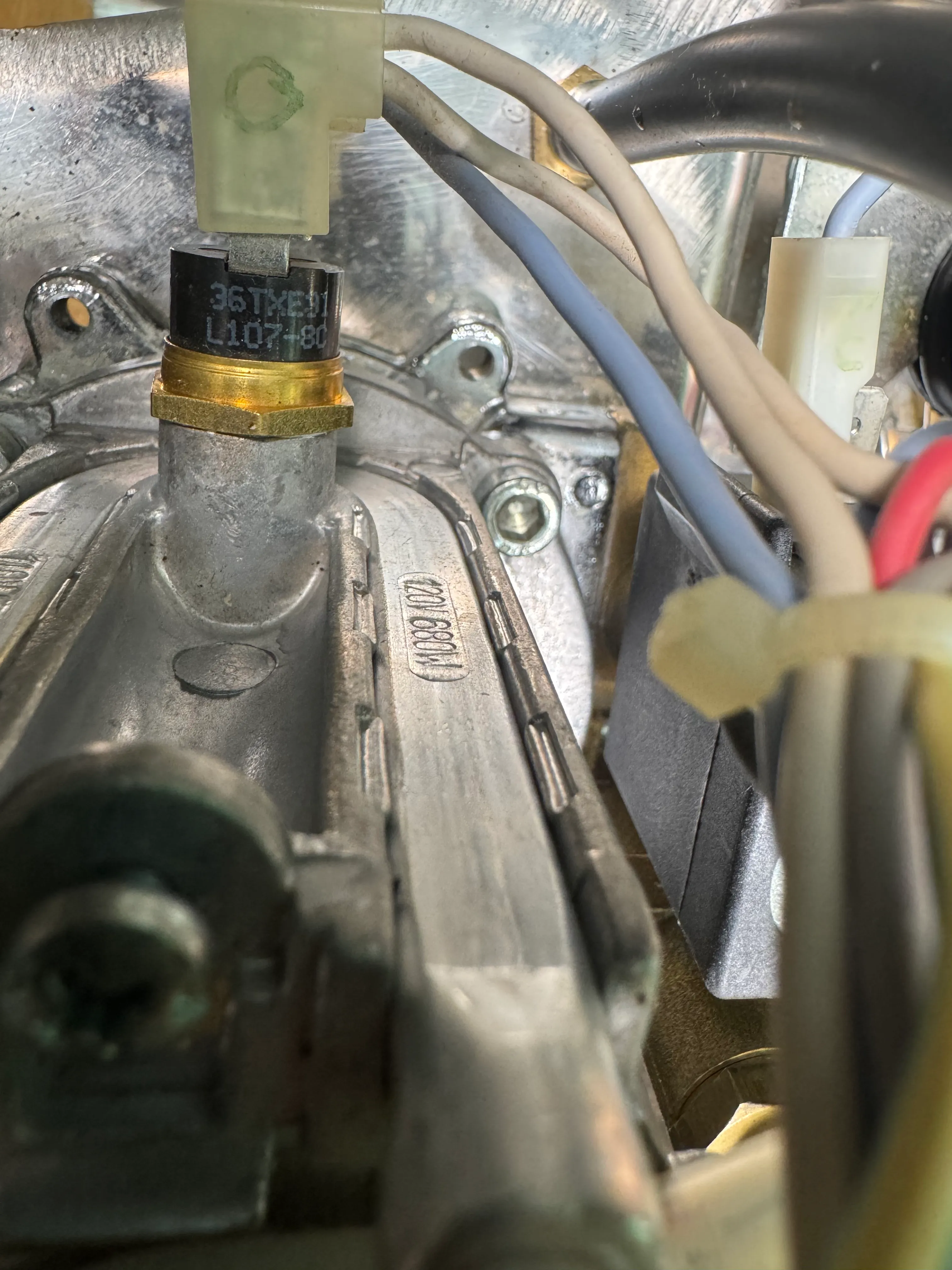
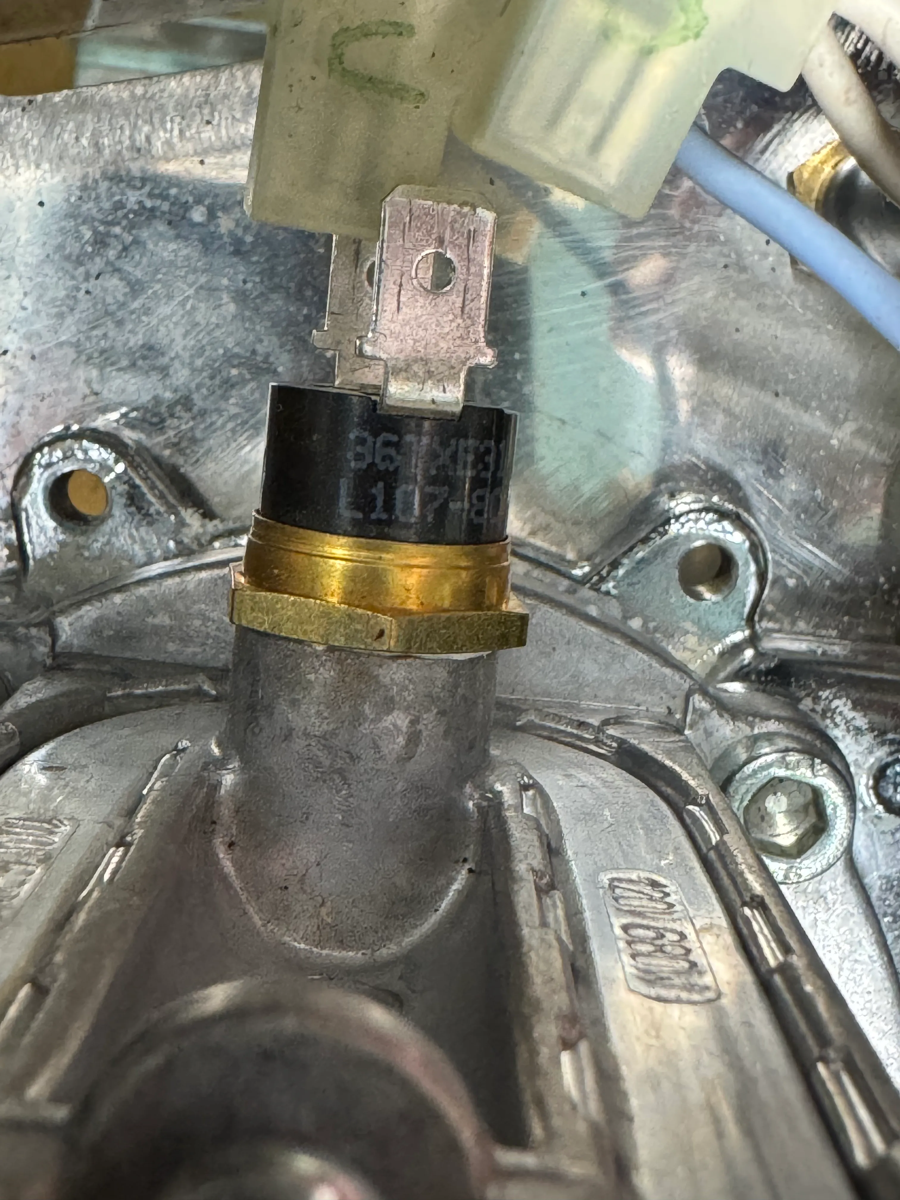
2 Steam thermostat
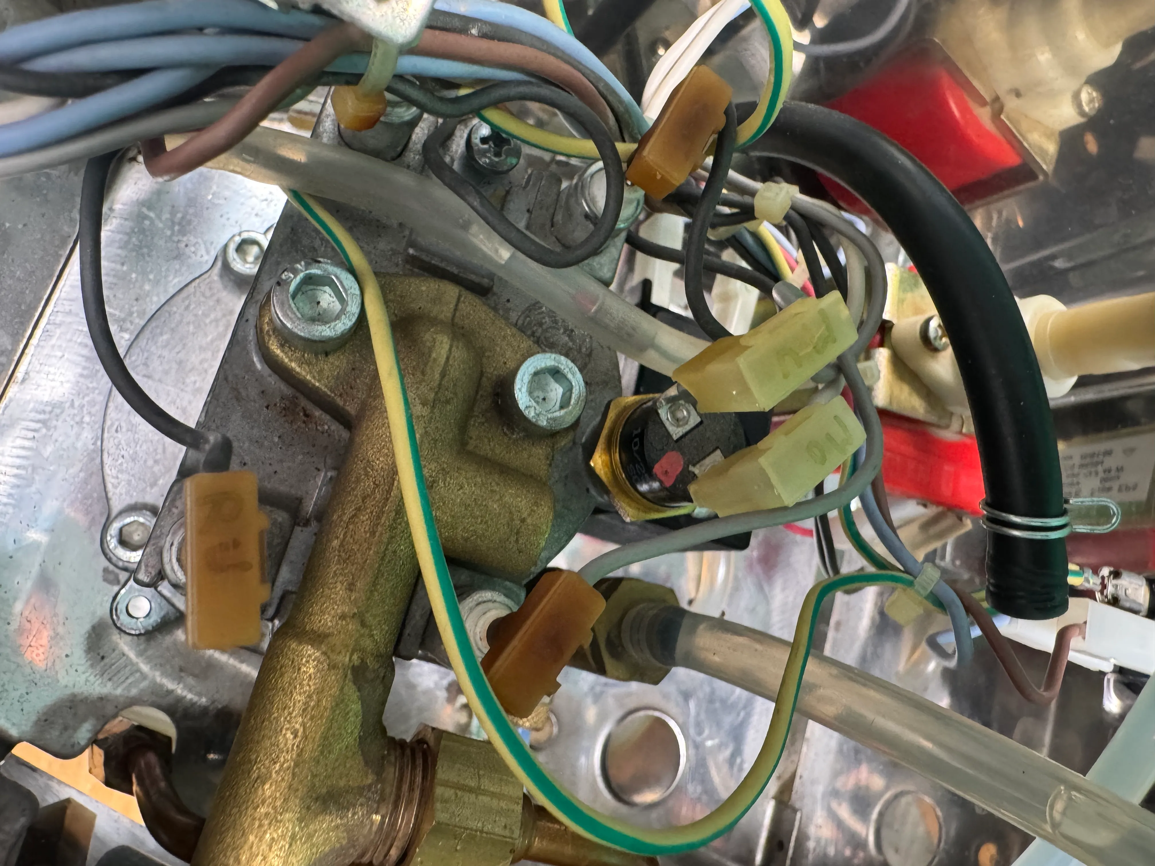
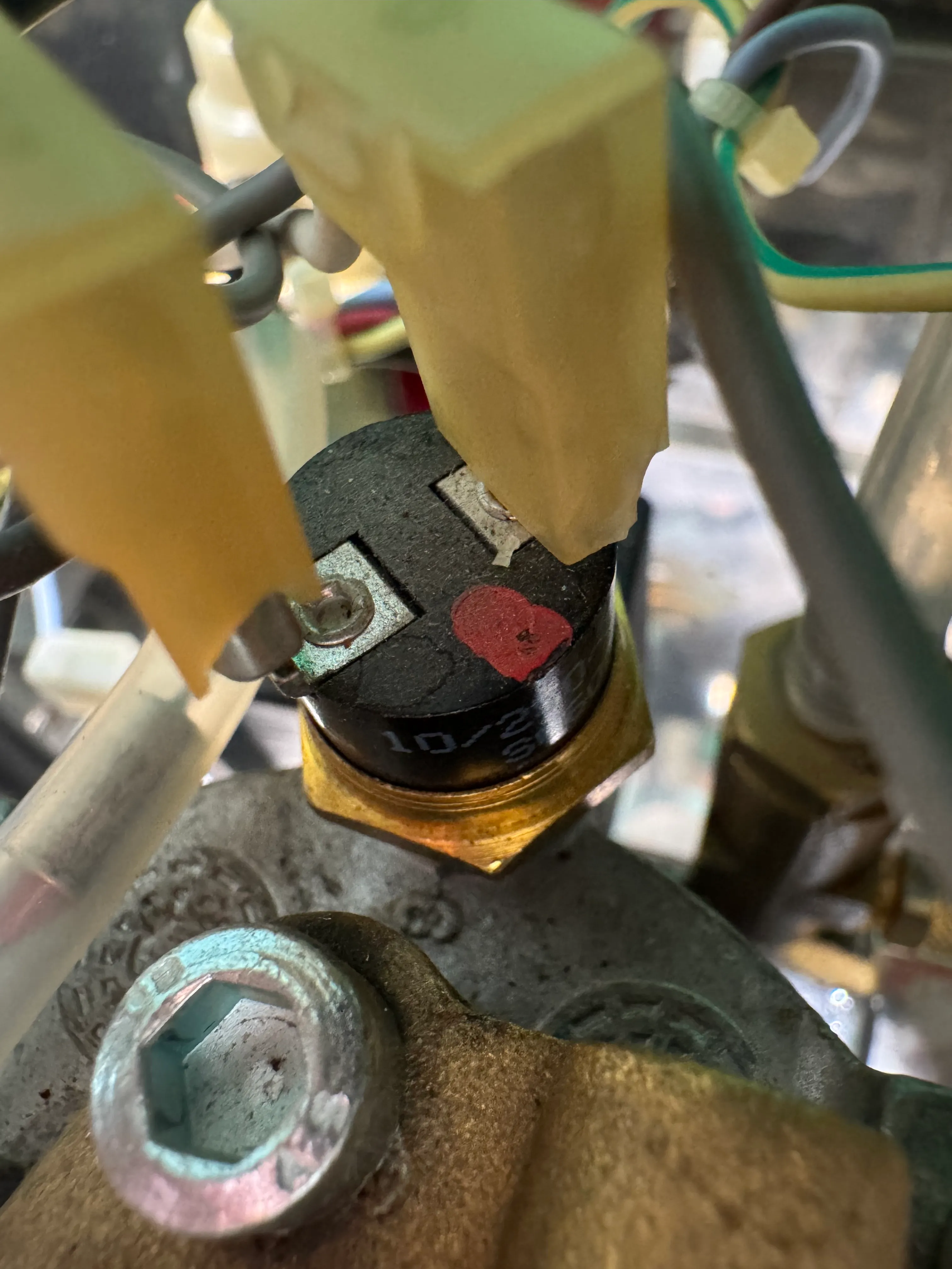
Find the steam thermostat on TOP of the boiler. Unplug the wires ST.A and ST.B.
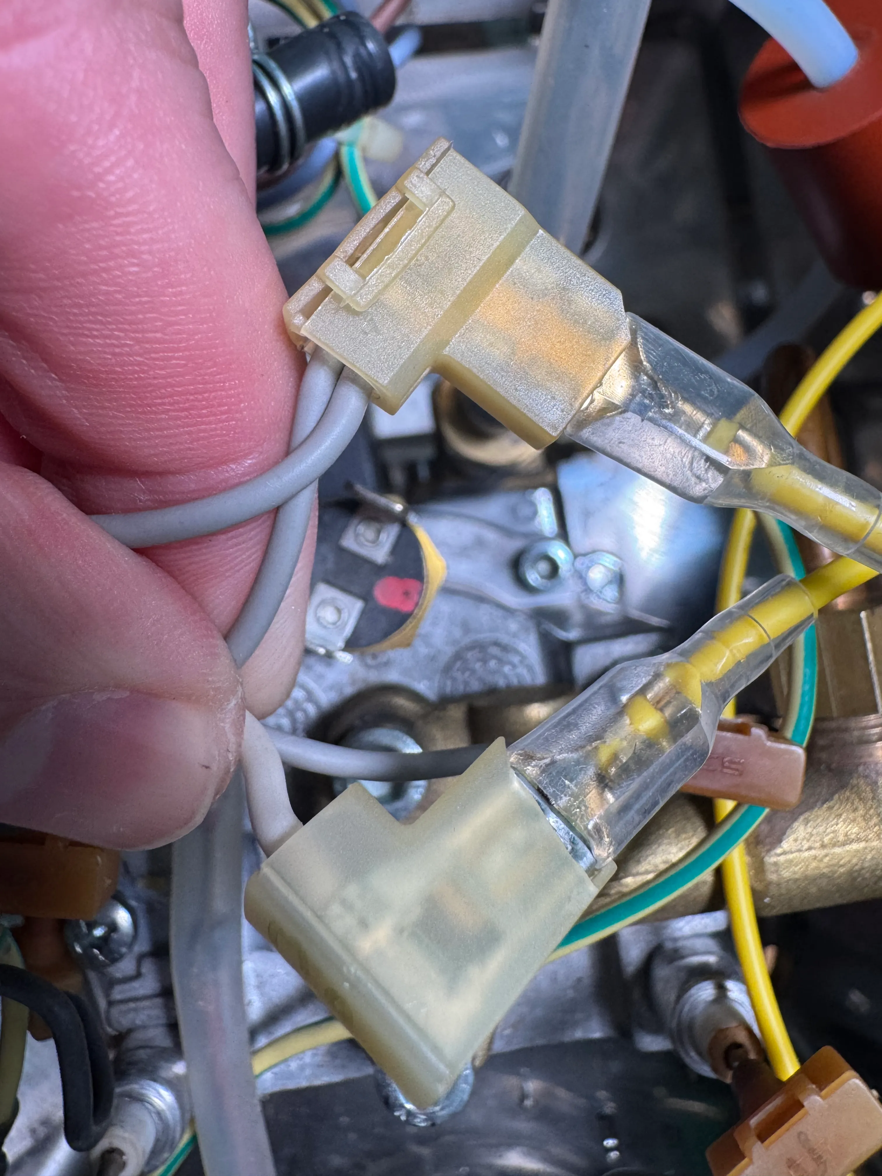
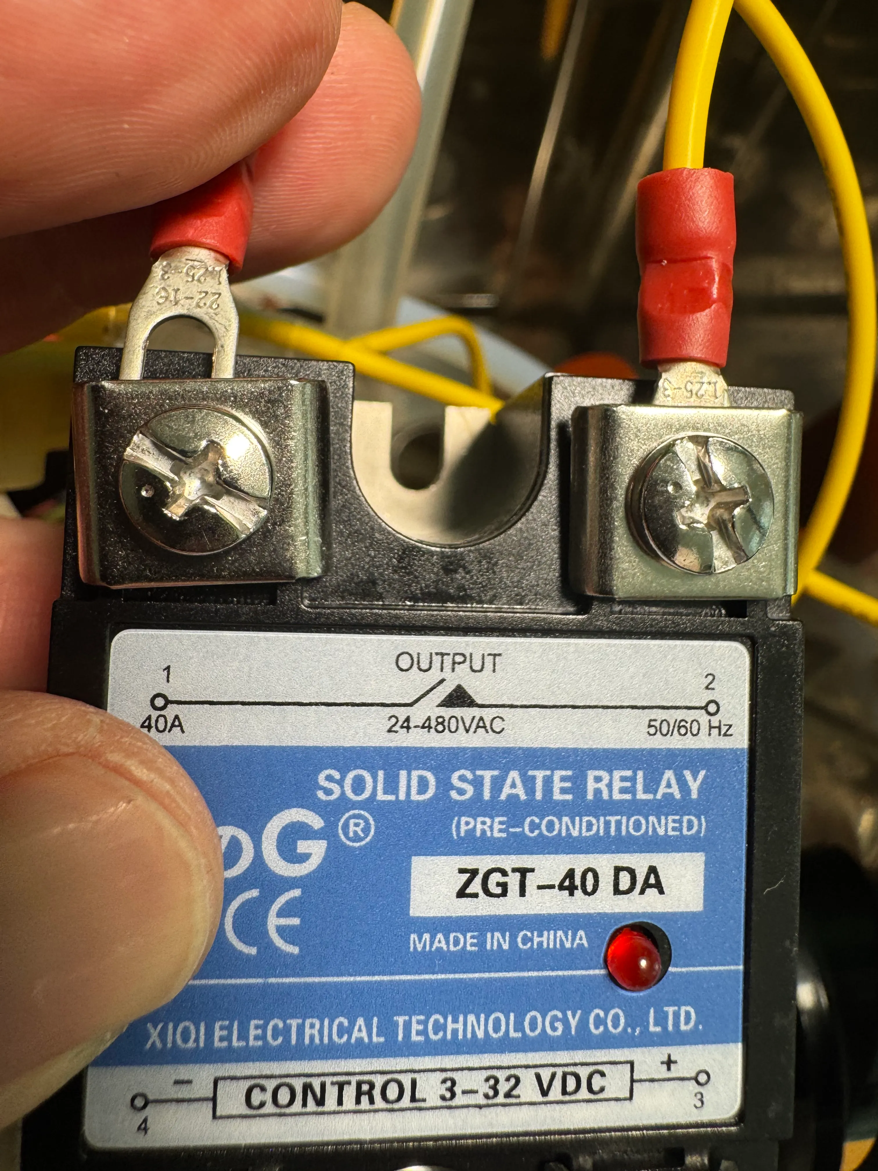
Extend each of the wires ST.A and ST.B with the yellow Heater to SSR cable Plug the spade end of the yellow Heater to SSR cables into the OUTPUT side of the SSR and tighten the screws. The thermostat can remain in the boiler or (recommended) be removed.
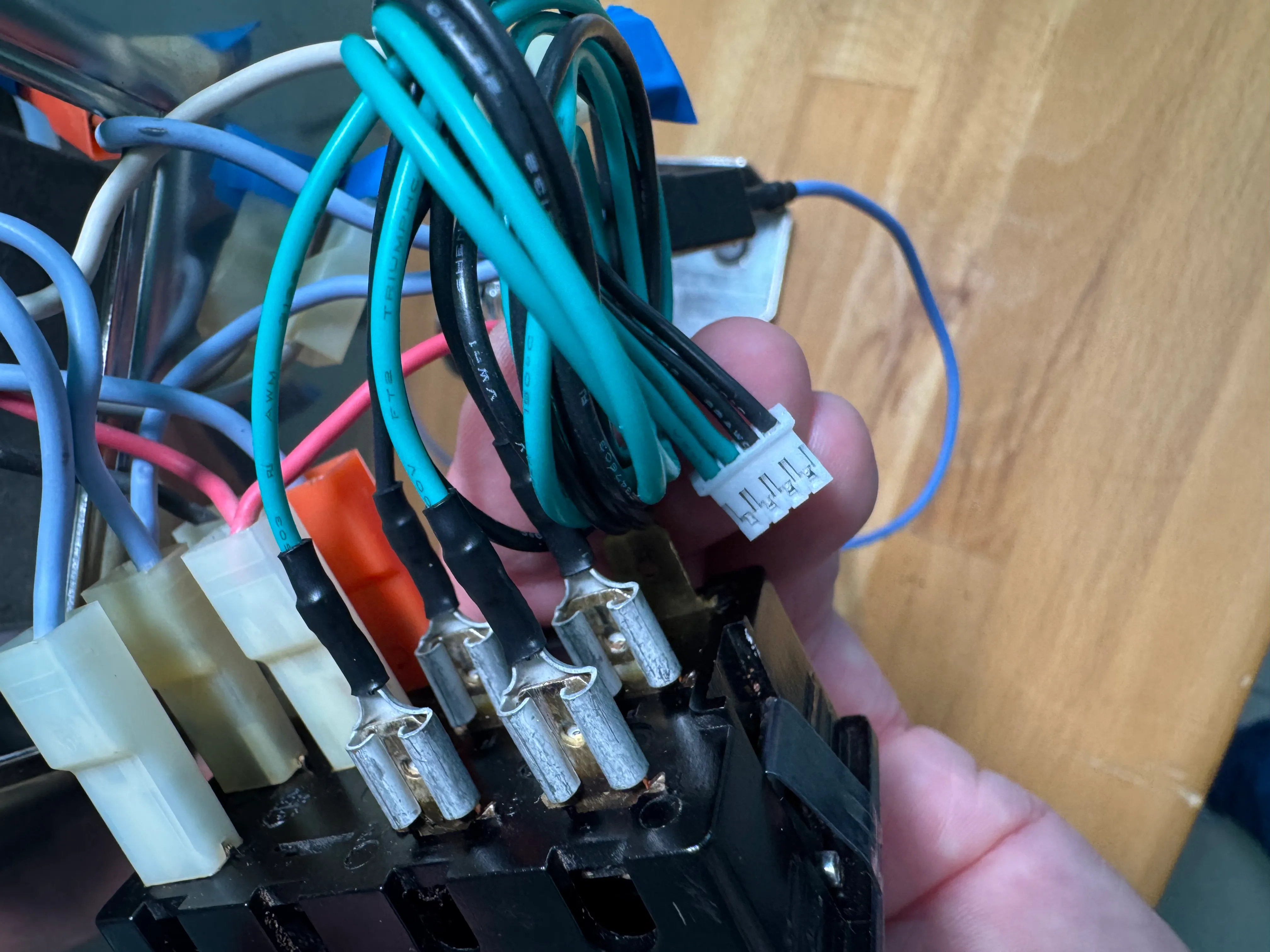
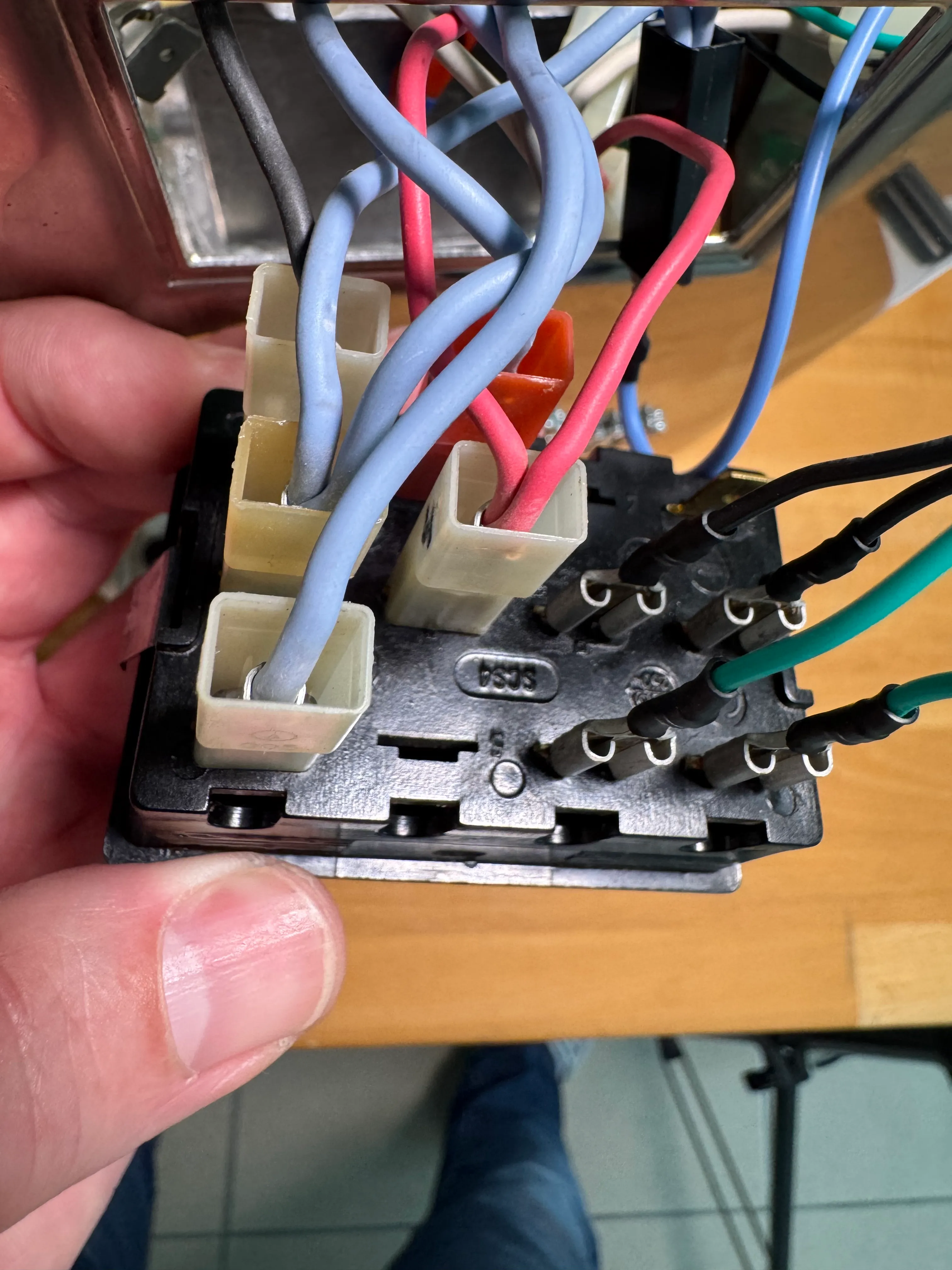
3 Switches / buttons sections
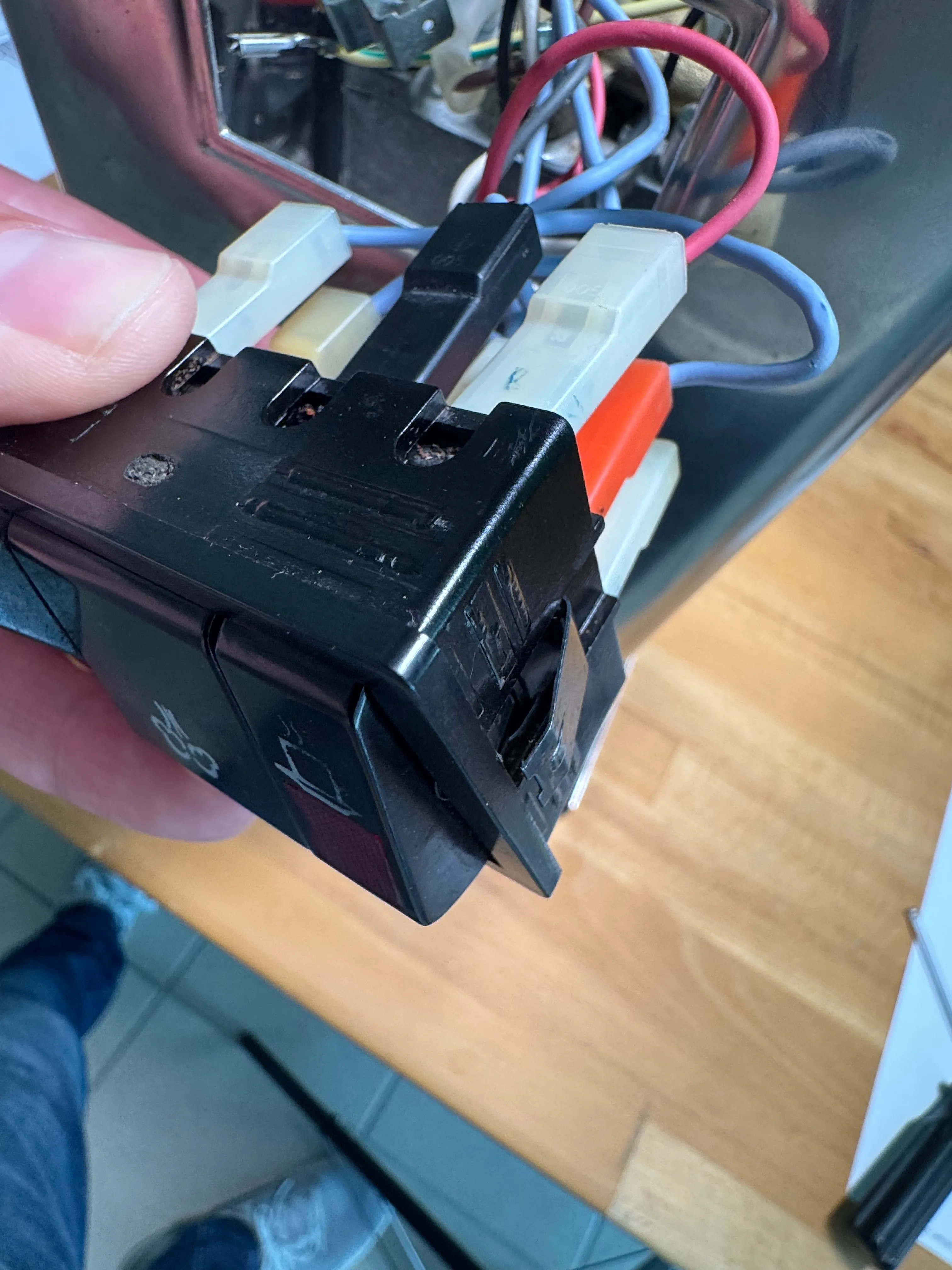
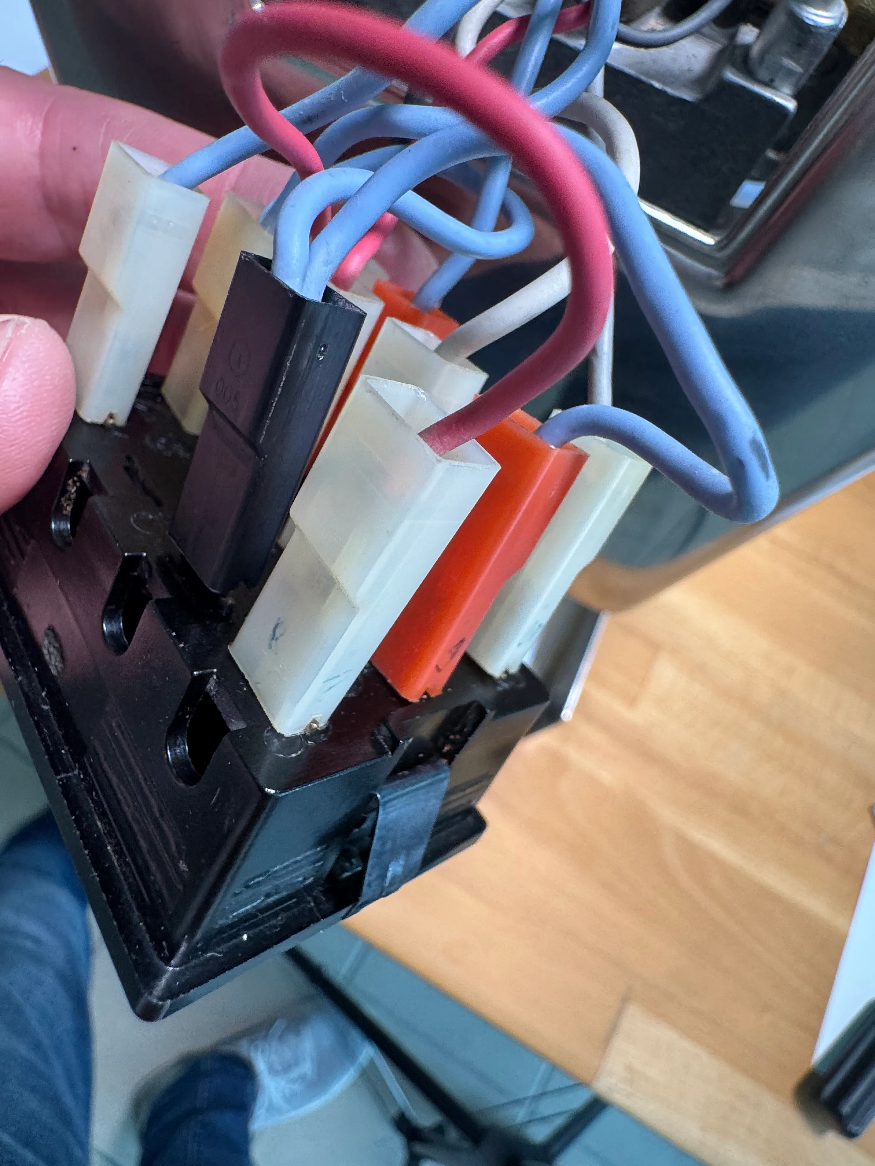
Pull the switches section out a little and tilt it towards you.
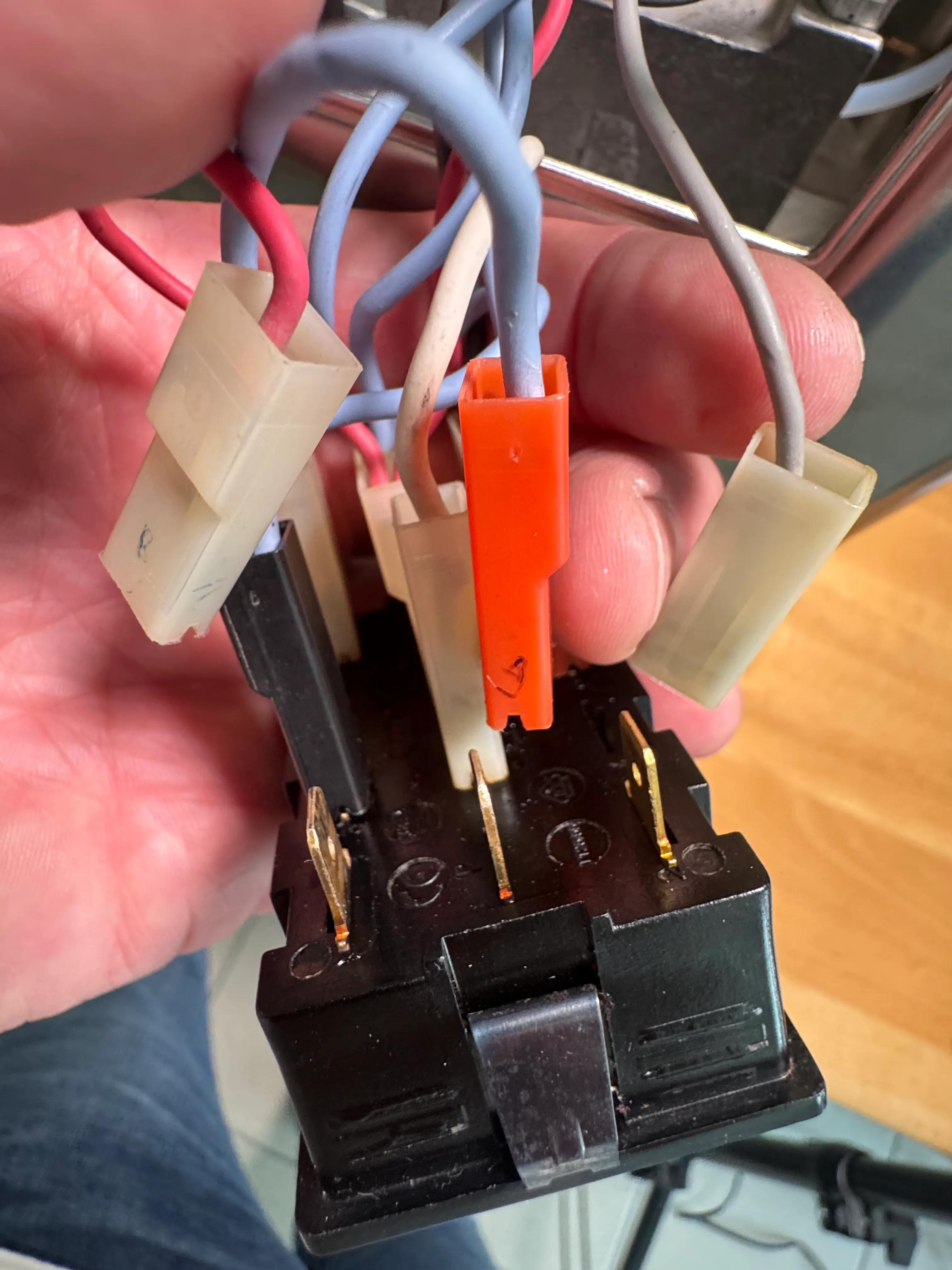
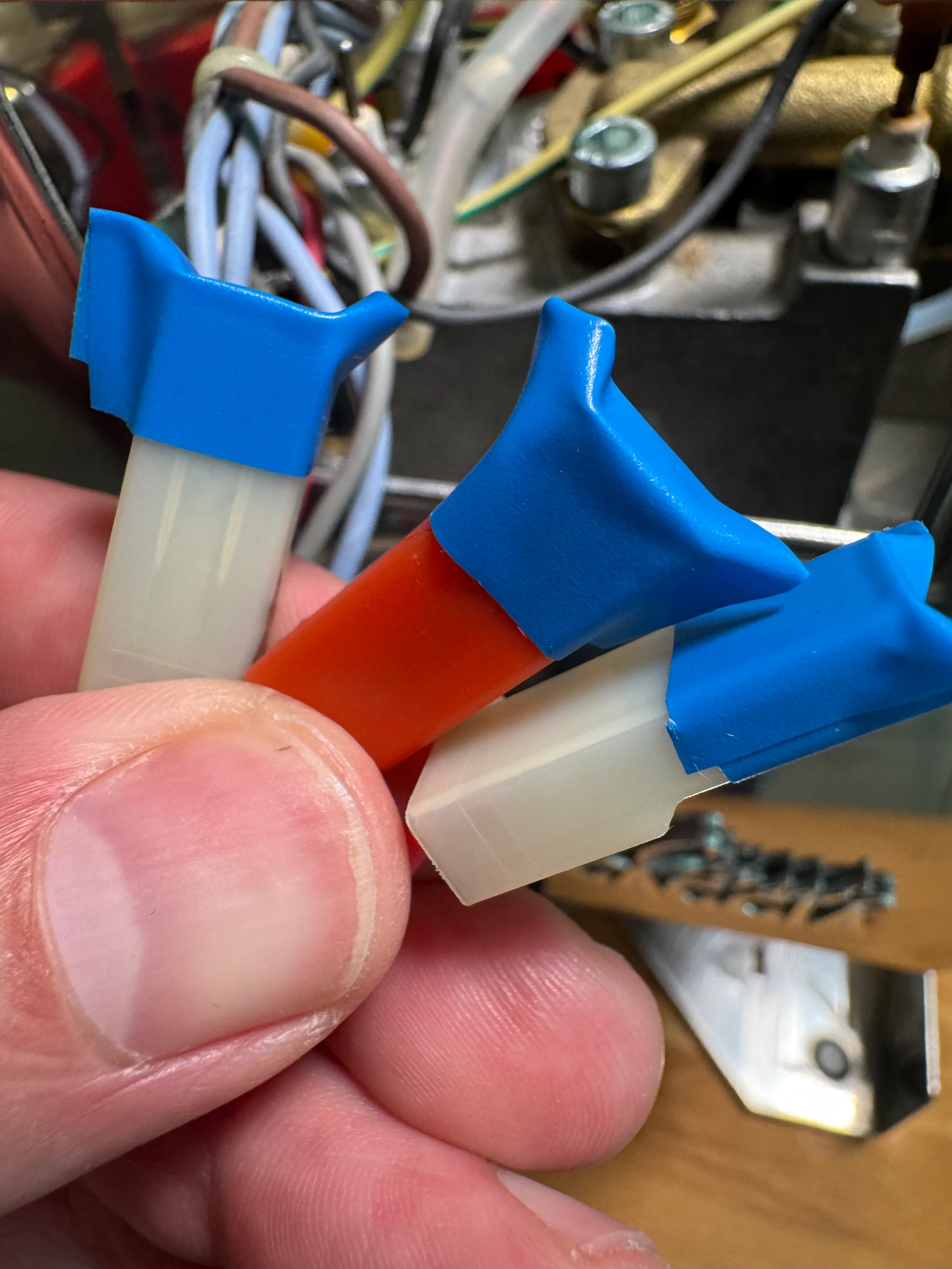
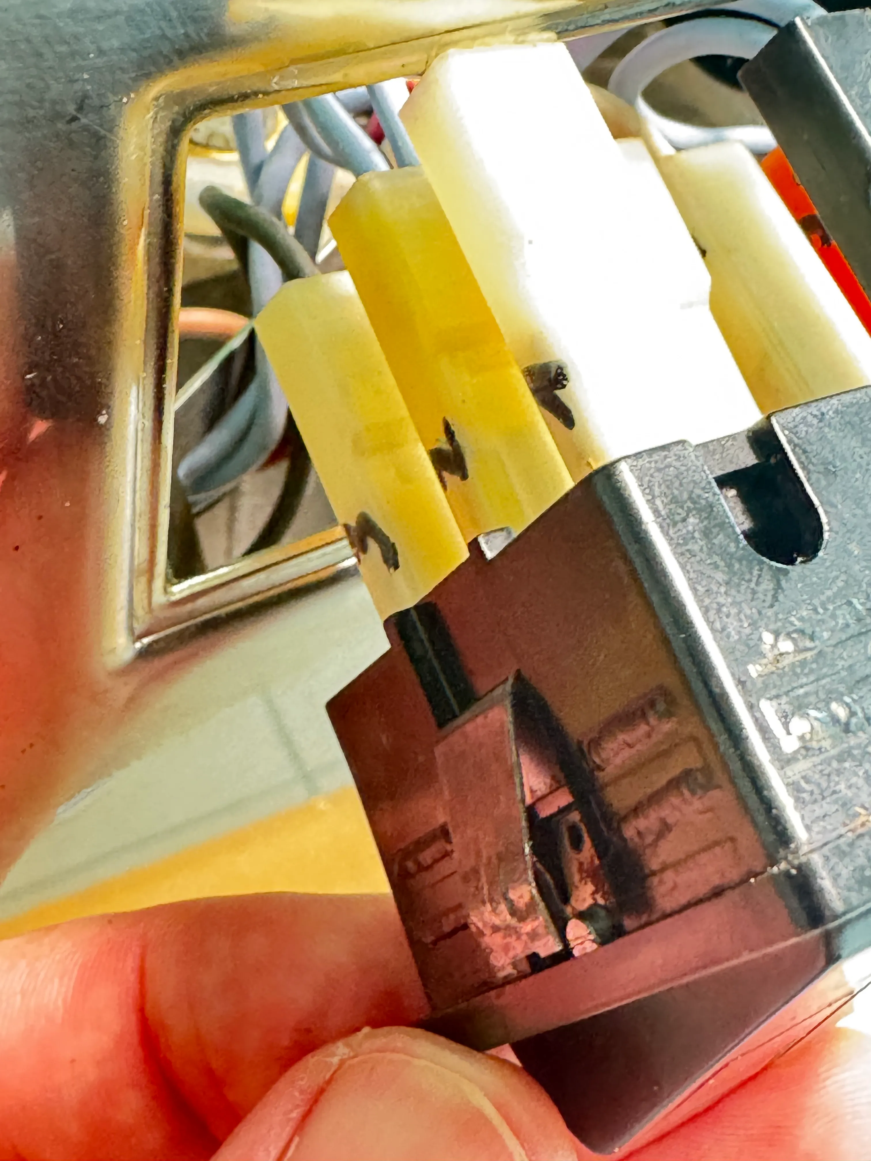
Unplug all connections in the right section (brew section: C.1, C.2, C.3) and insulate them.
4 Switches / buttons sections
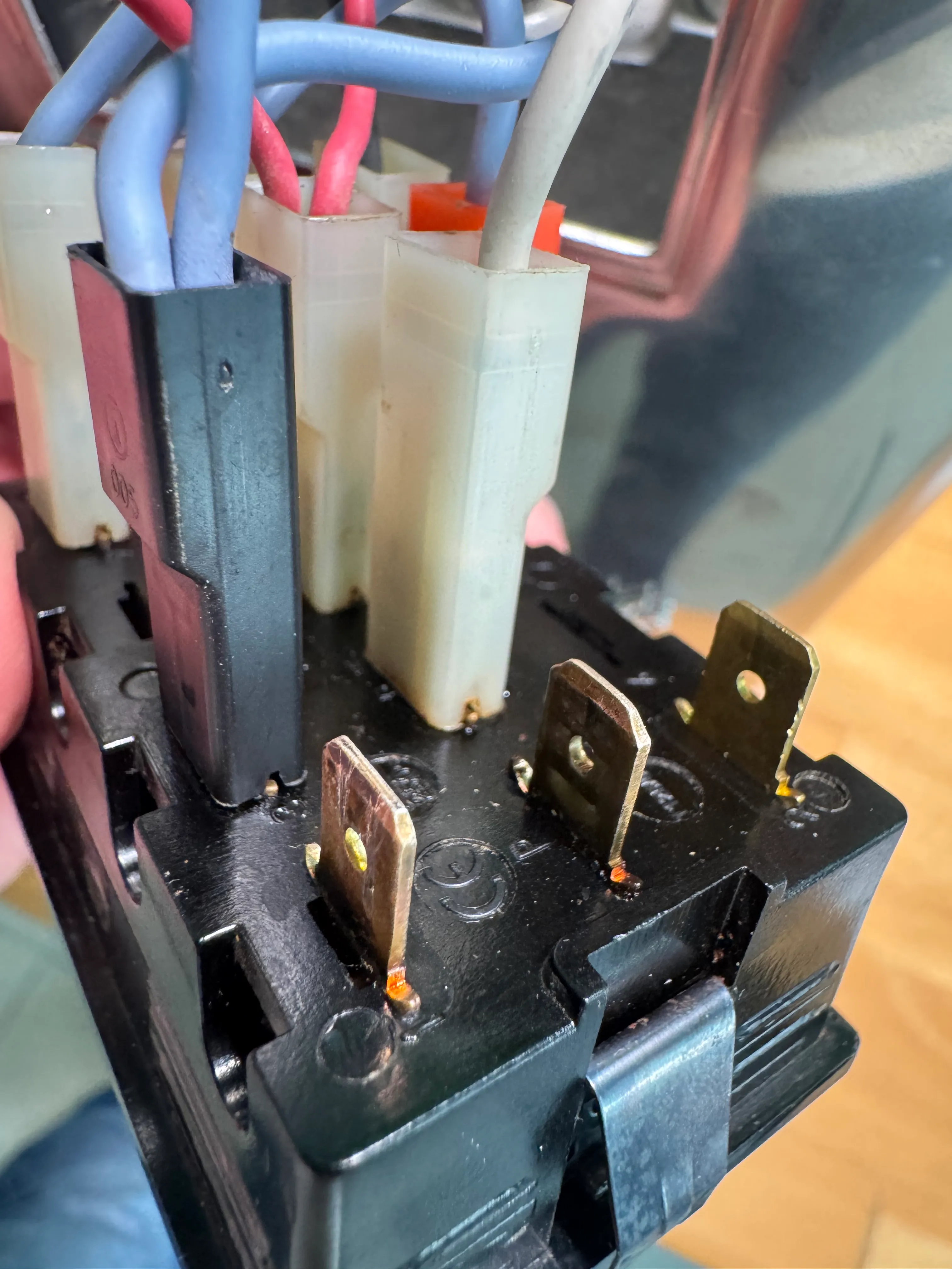
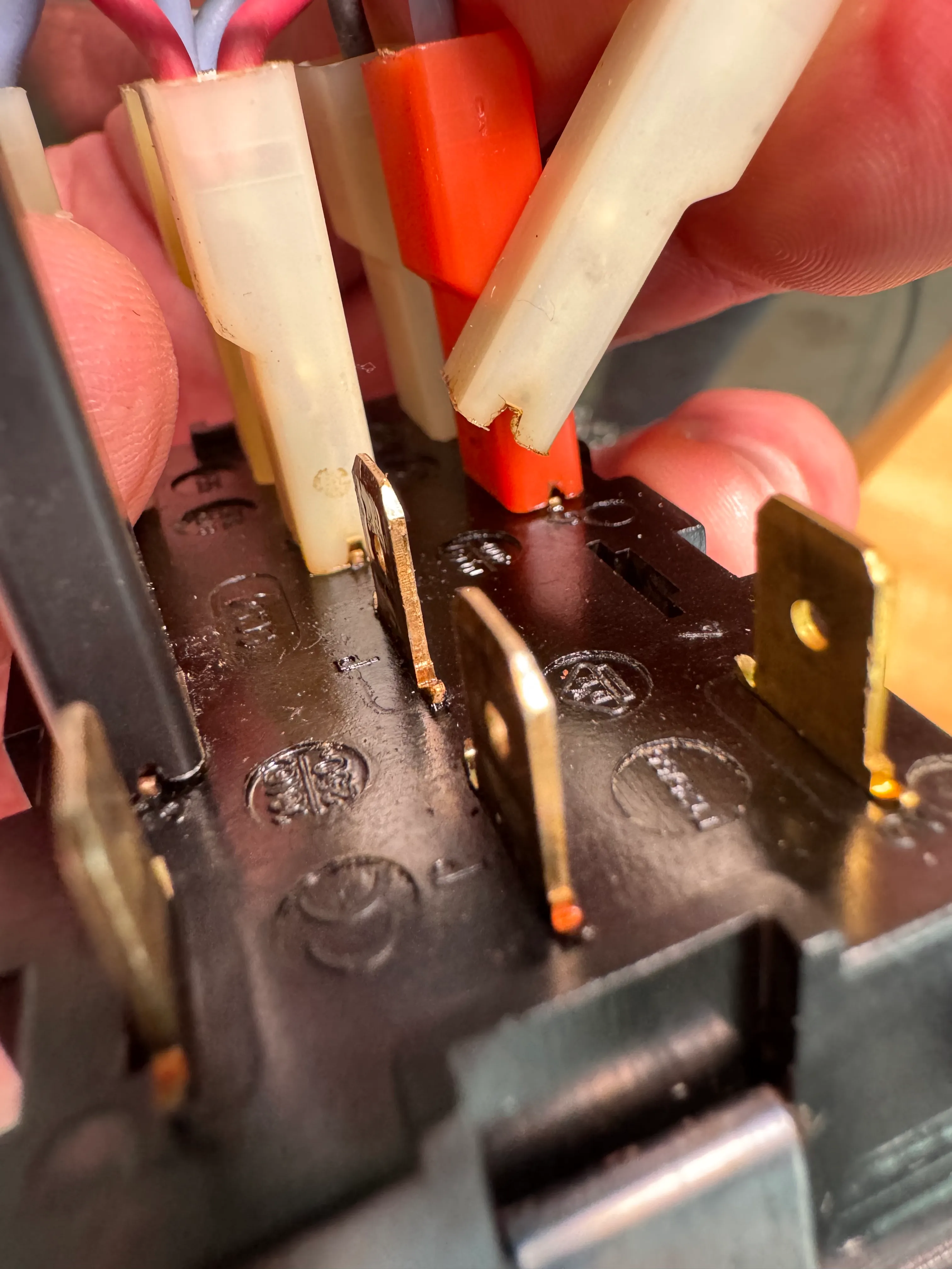
Unplug S.2 (lowest in the 2.nd row from right) and insulate it.
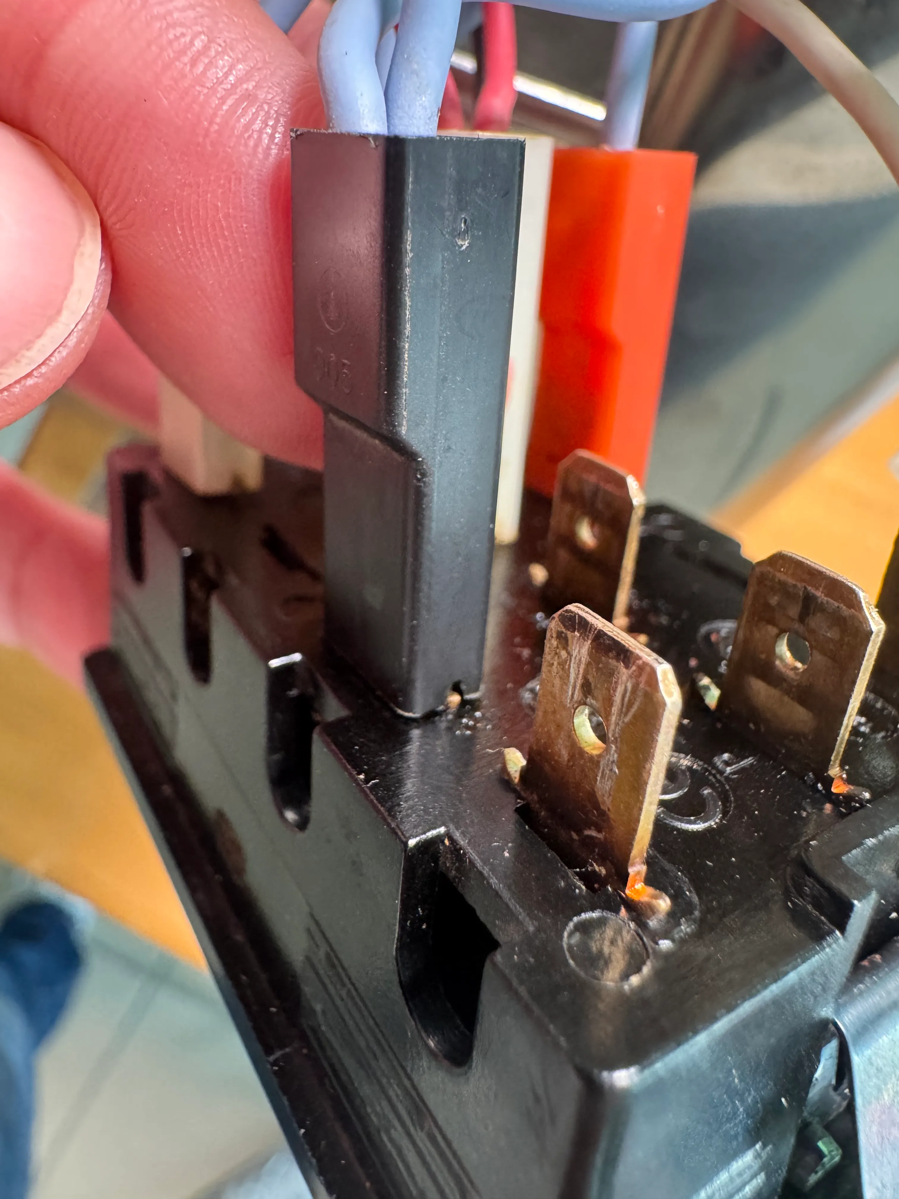
5 Switches / buttons sections
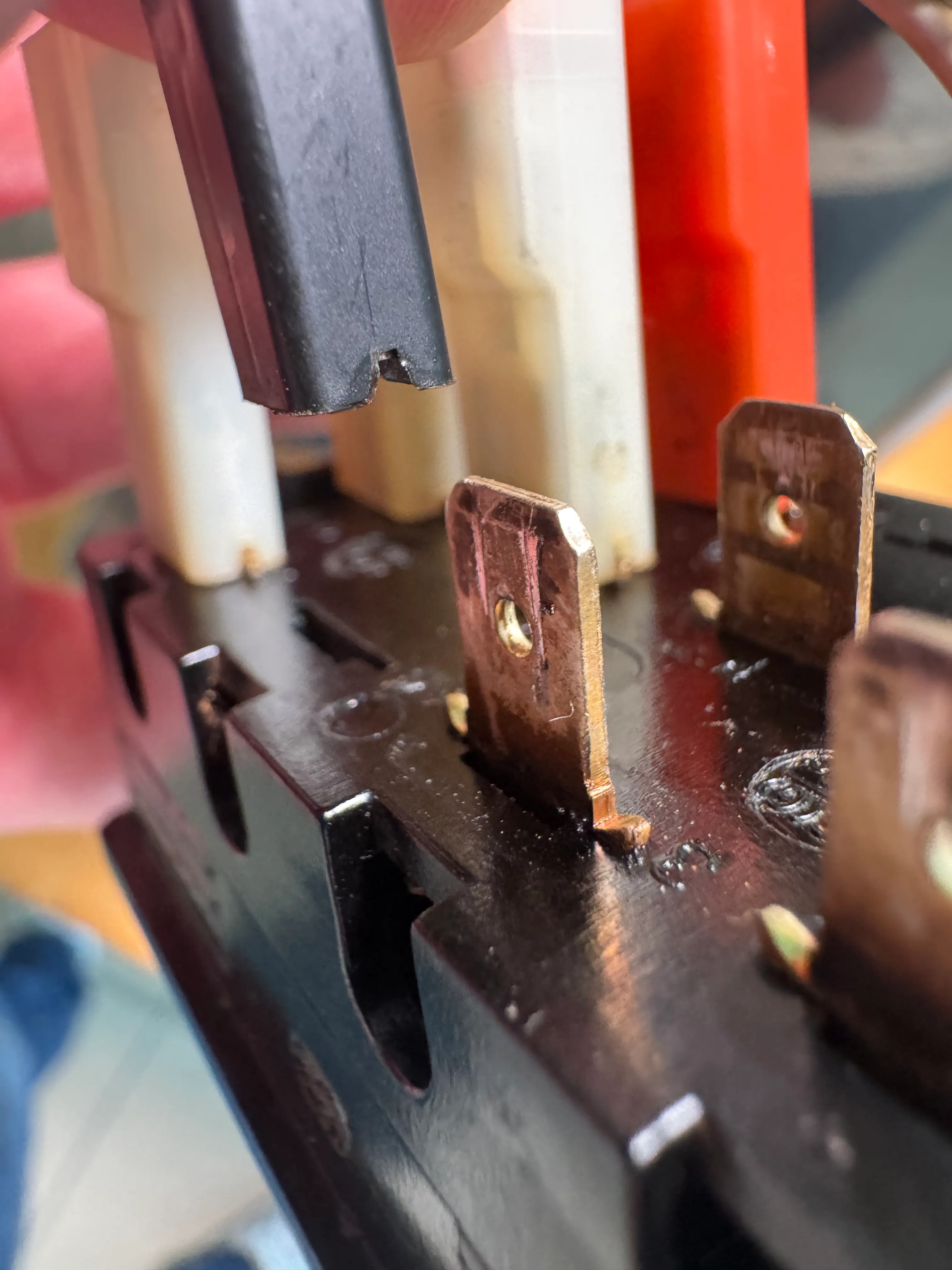
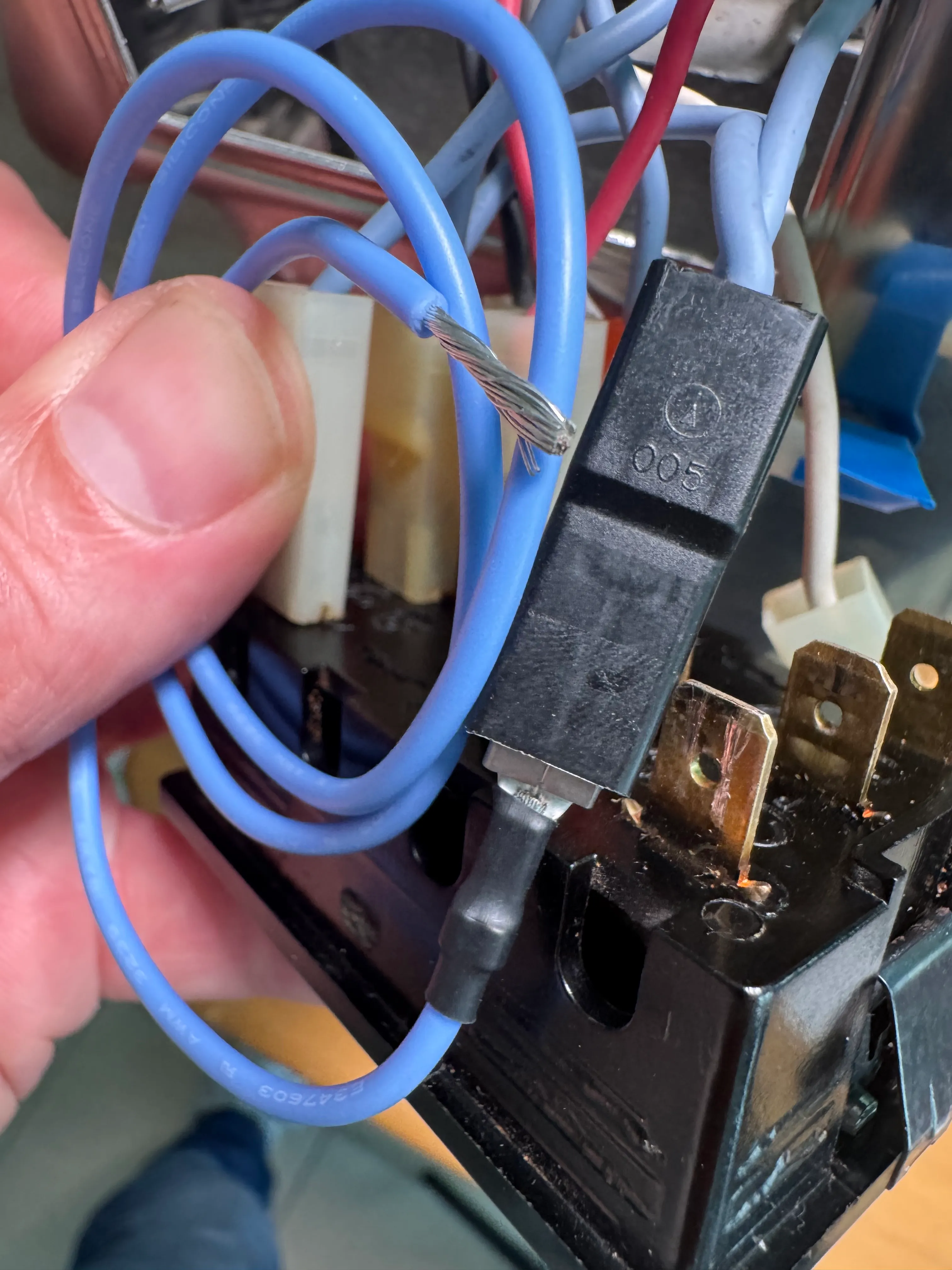
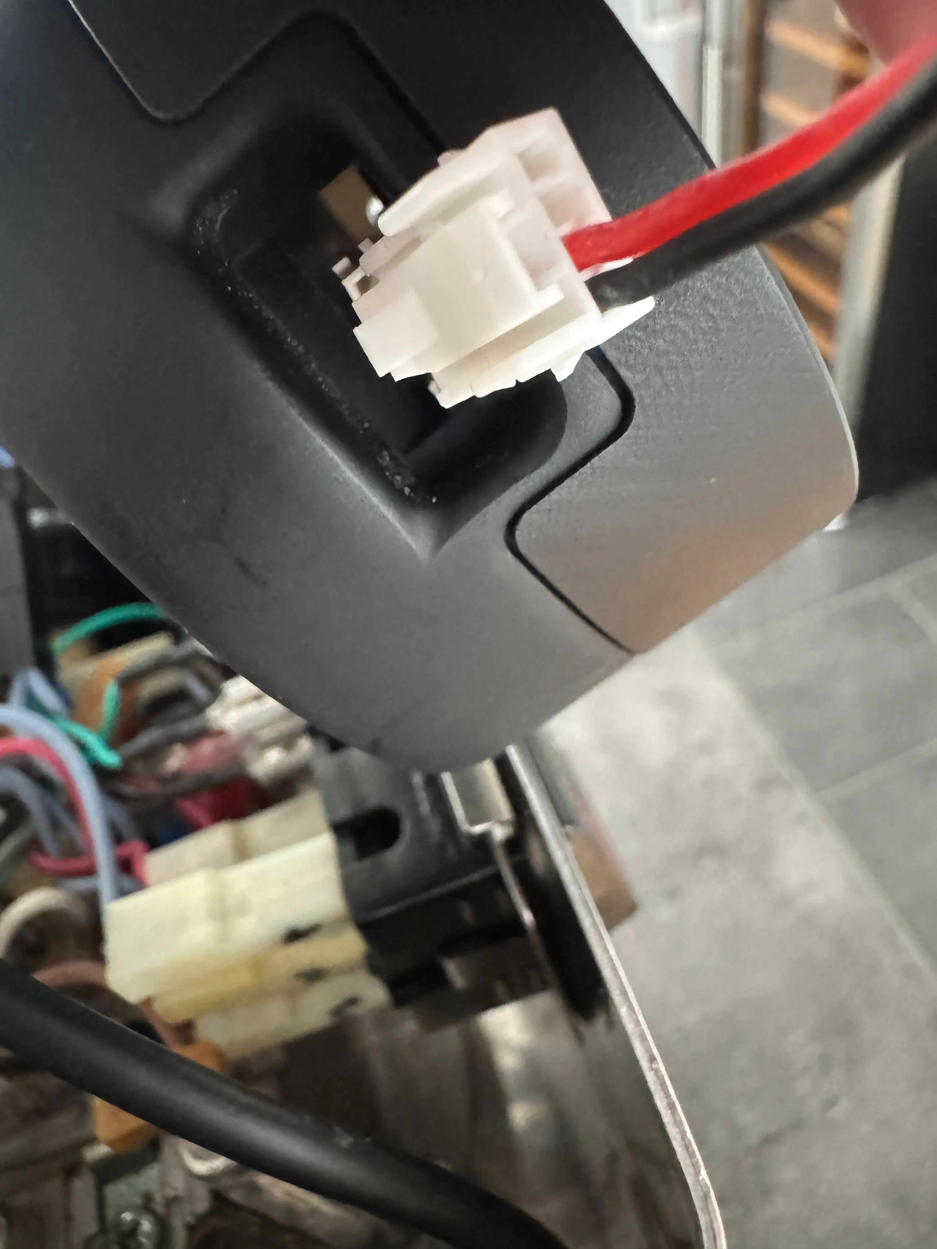
Unplug S.1. Extend it with the blue Flat con cable.
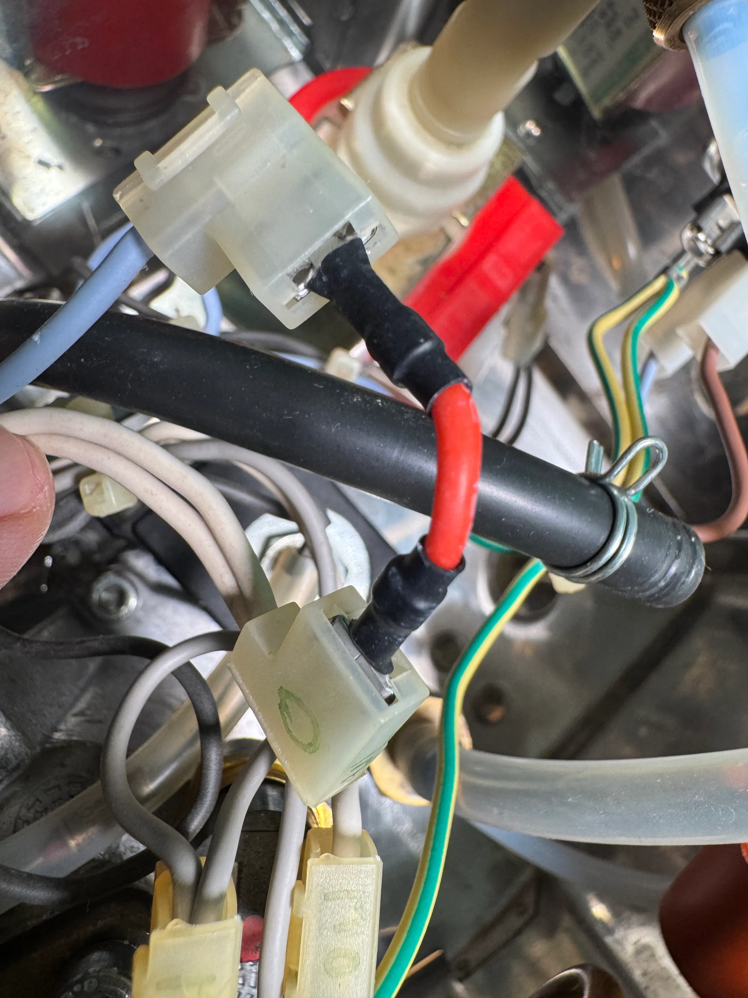
6 Pump connections
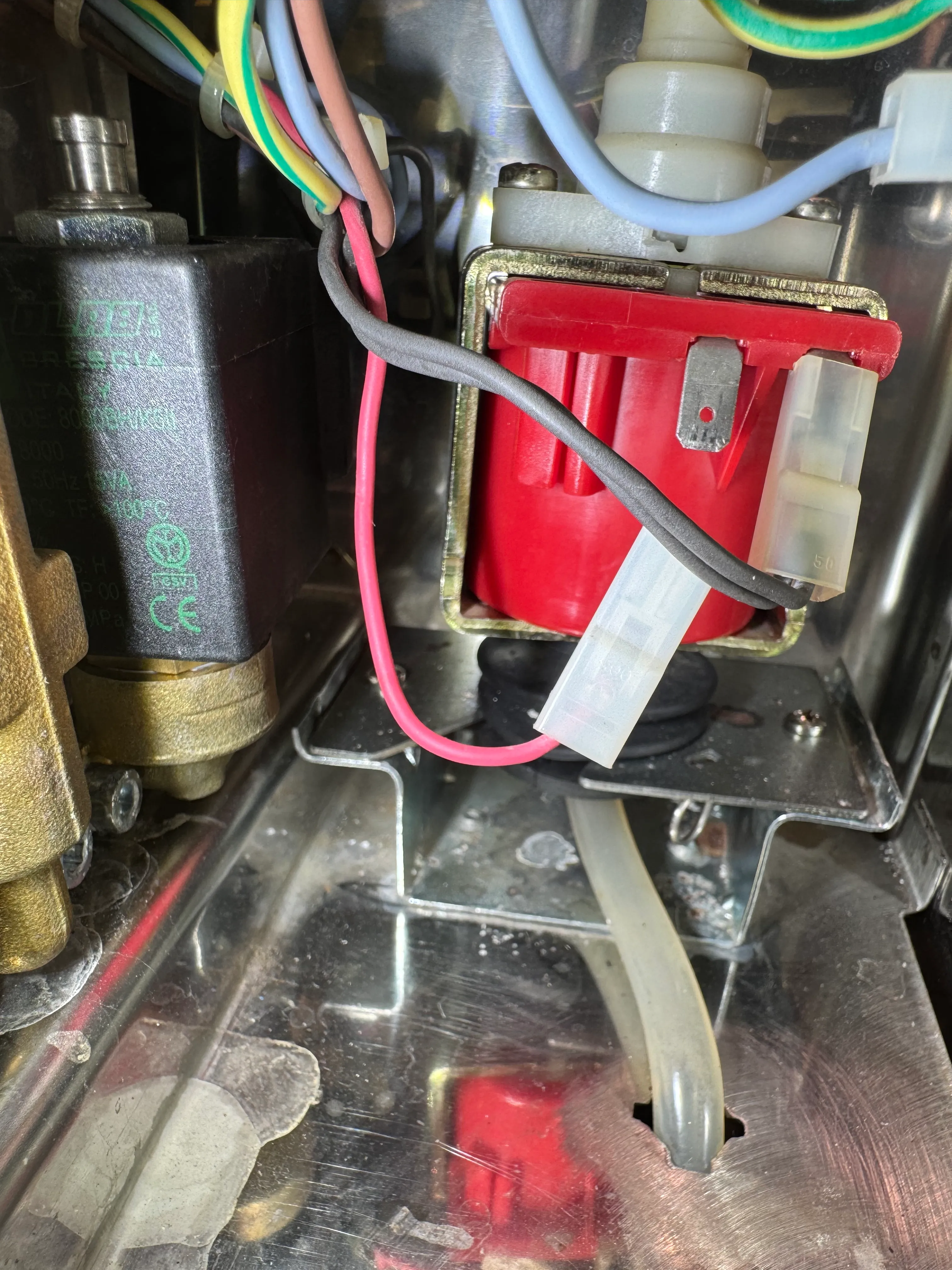
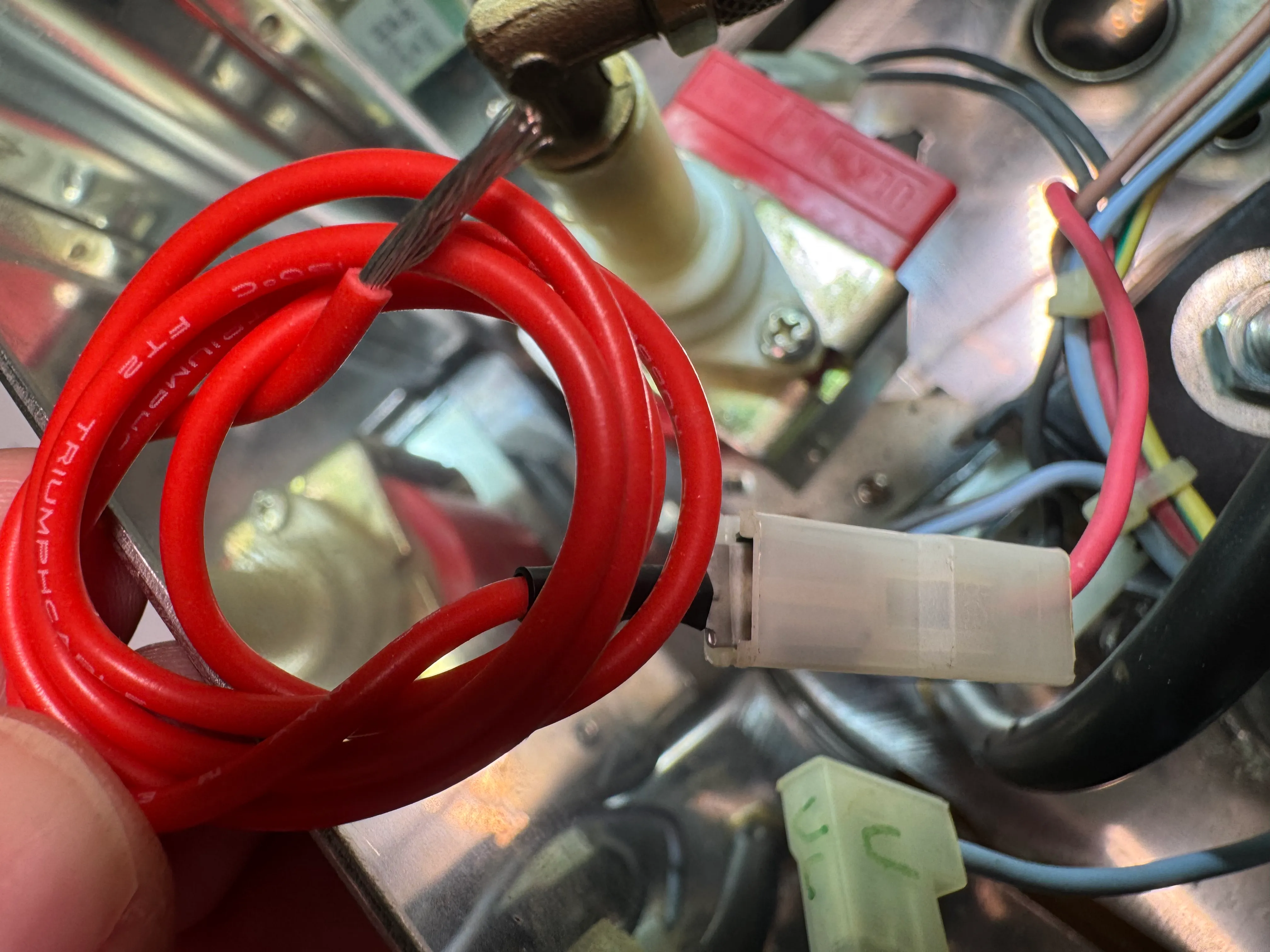
Find the pump. Unplug the PMP.B cable (the one that has only one wire) Extend it with the red Flat con cable.
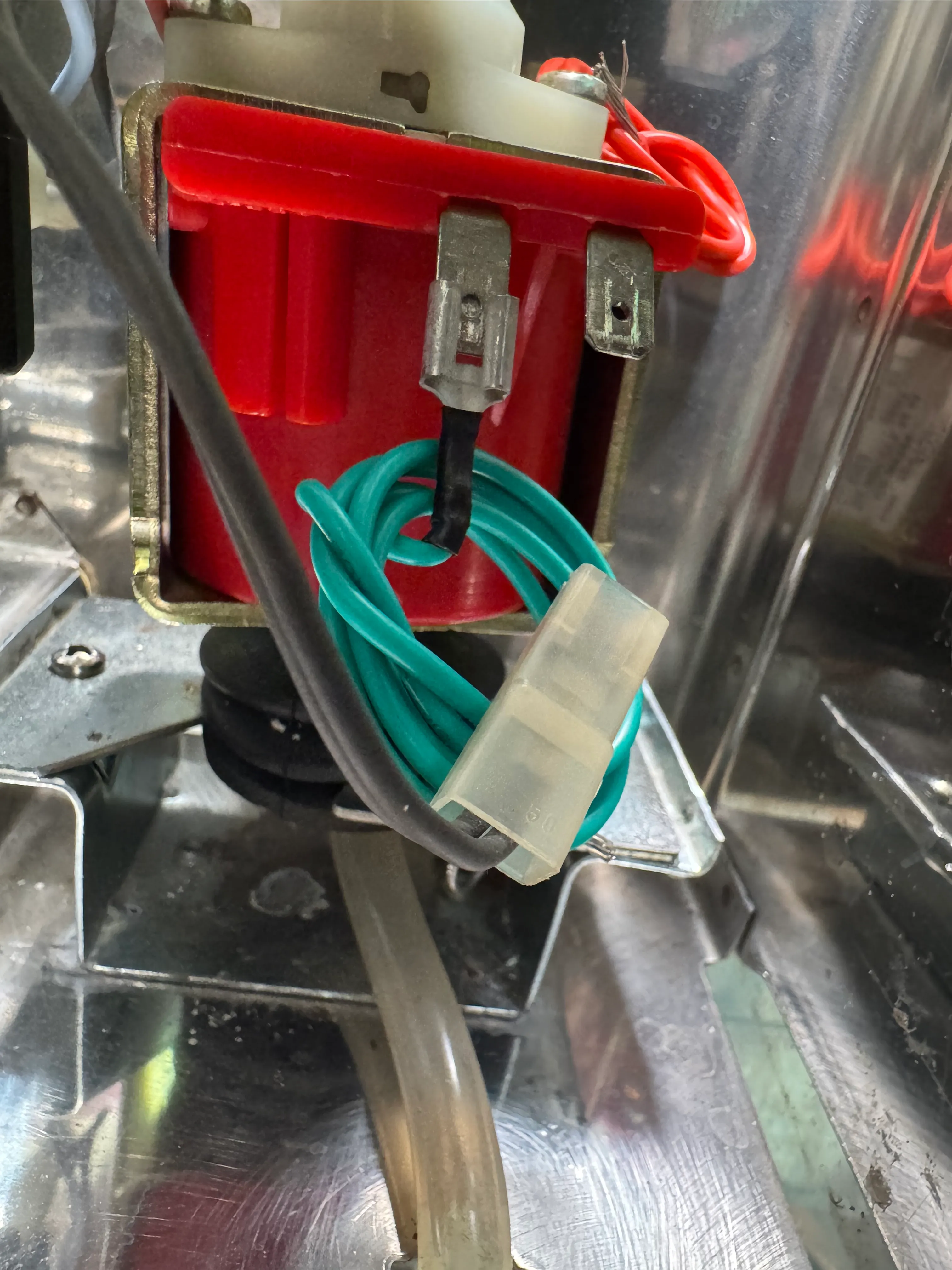
7 Pump connections
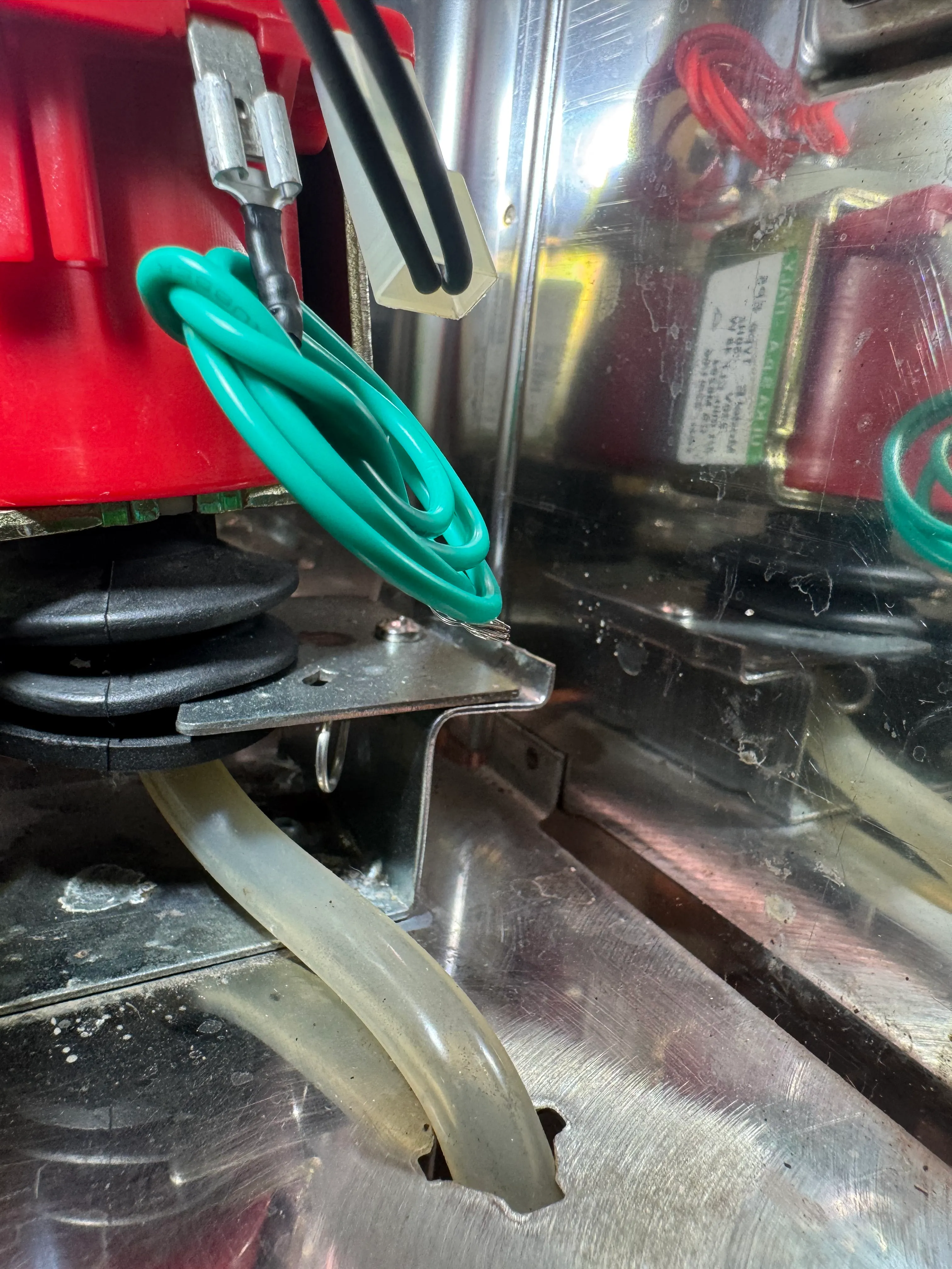
Plug the green Pump cable into the now free PMP.B socket of the pump.
8 Pump connections
Unplug the dark gray PMP.A cable from the pump socket. Connect the dark gray PMP.A cable you just unplugged to the gray U-cable. Plug the female connector of the grey U-cable into the now free PMP.A socket of the pump.
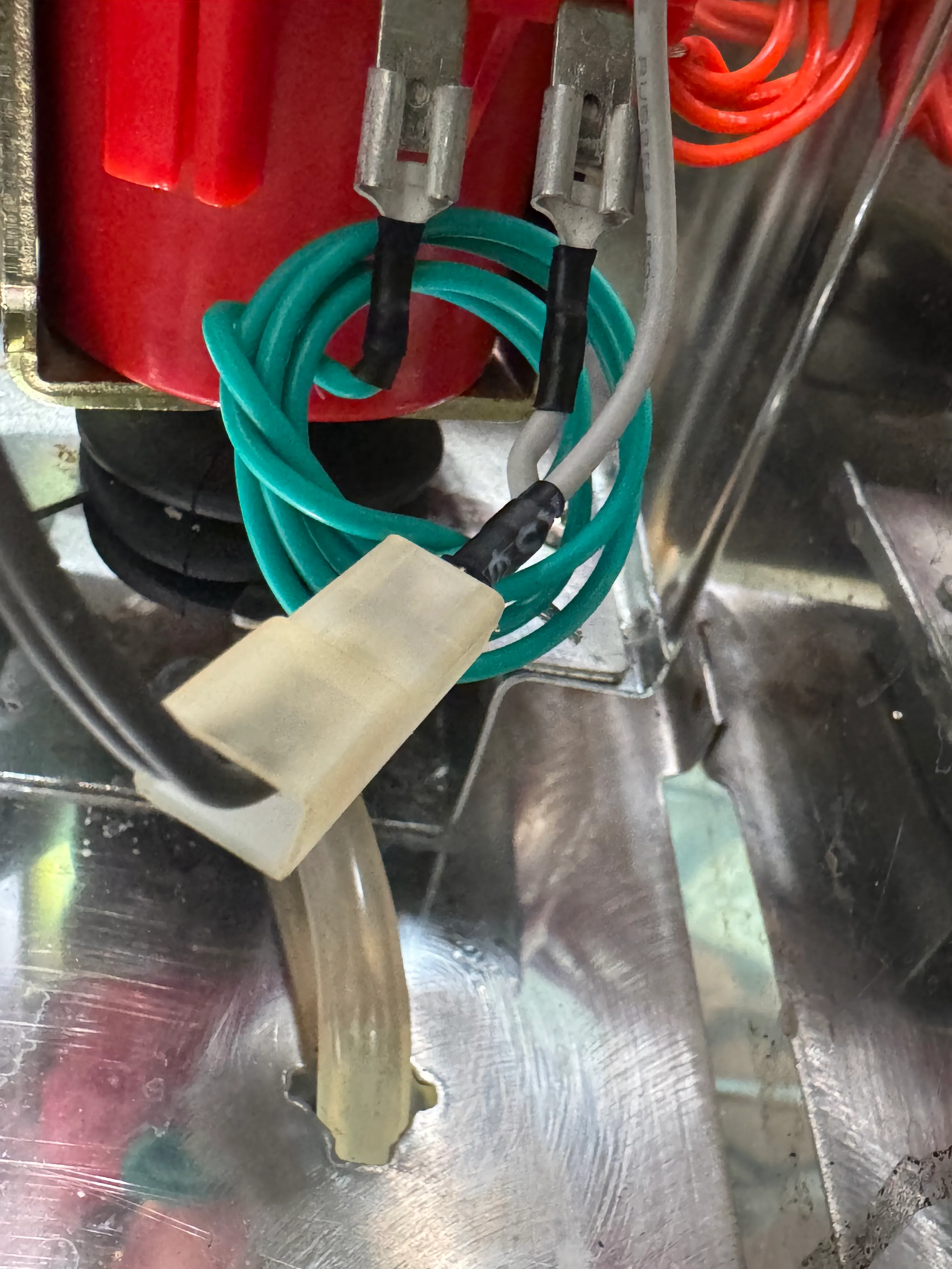
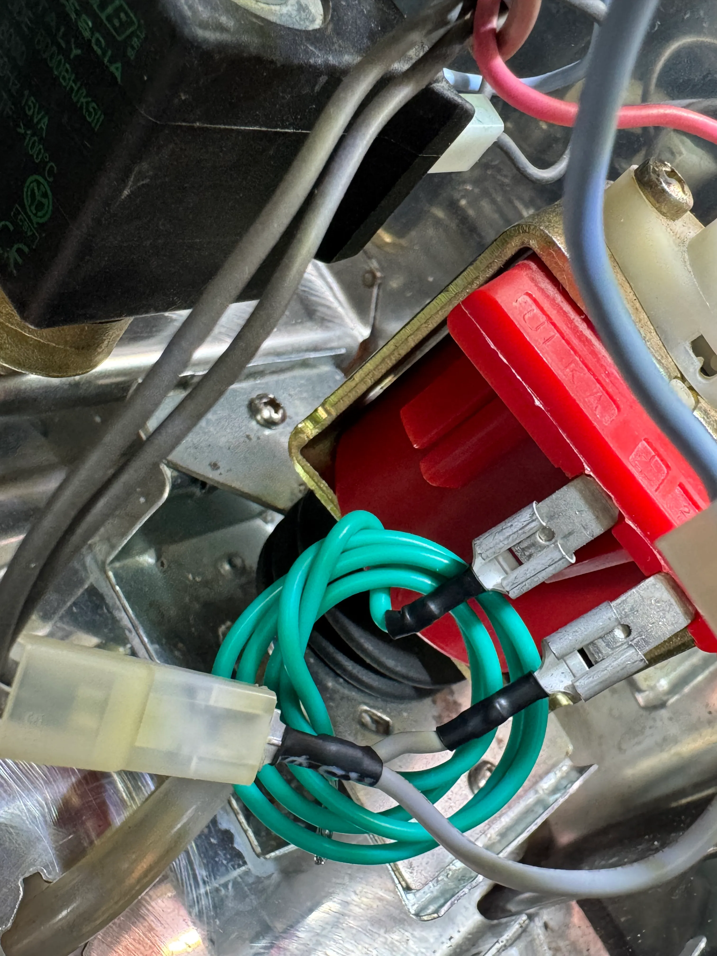
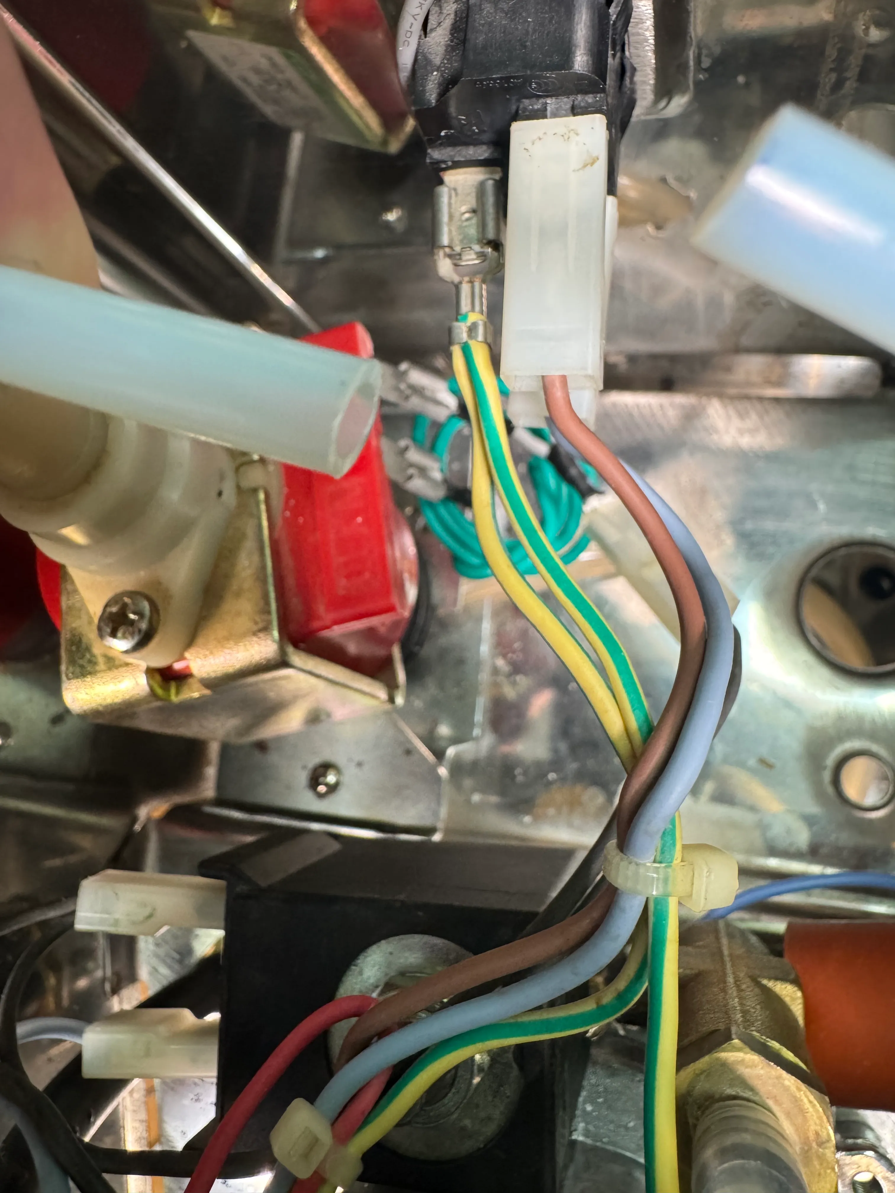
9 Switches functionality

To keep the switches operational, plug the Buttons cable into the switches section as follows: Green BREW to C.1 Green STEAM to S.1 Black Gnd to C.2 Black Gnd to S.2
10 SSR signal cable
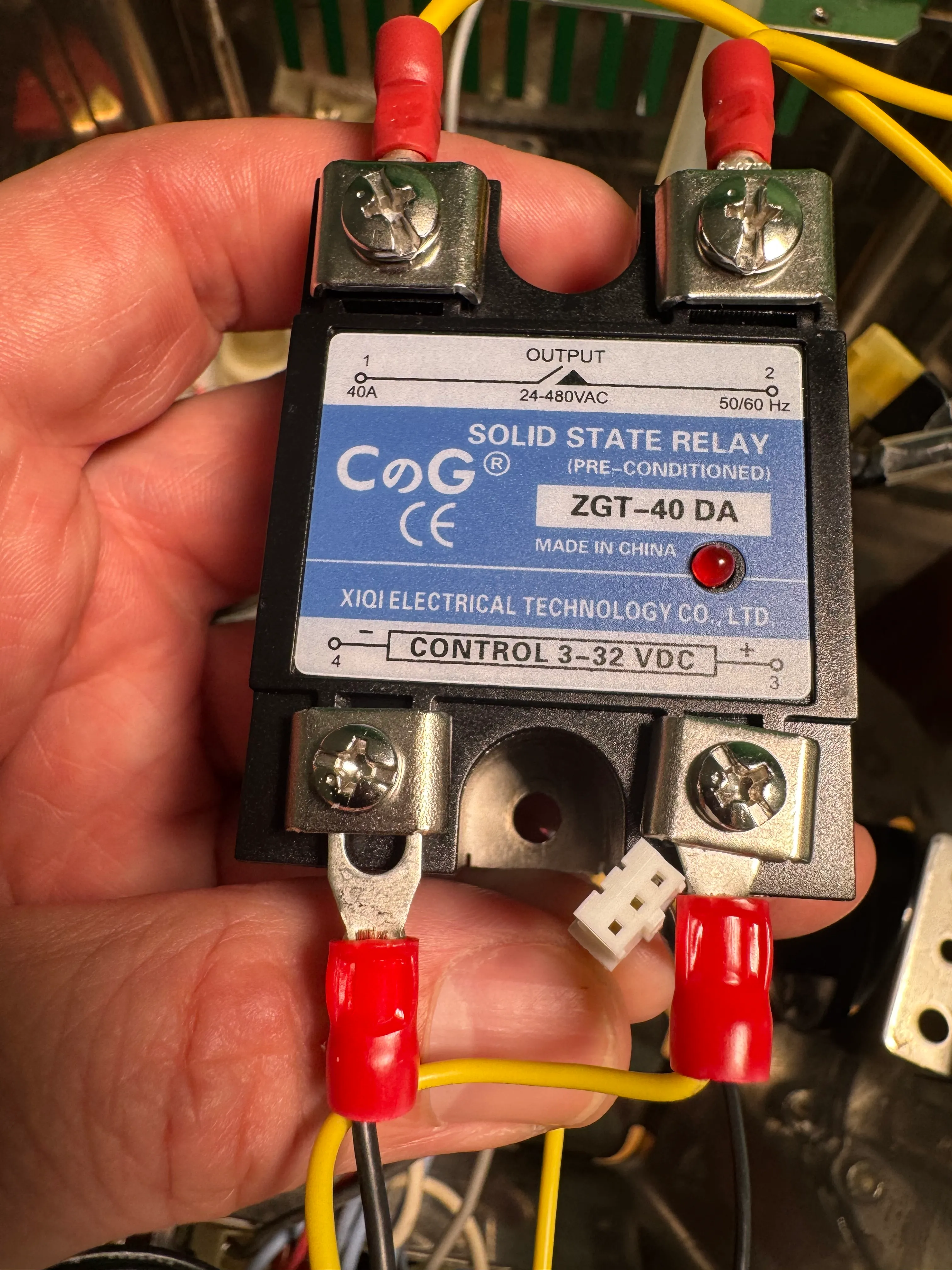
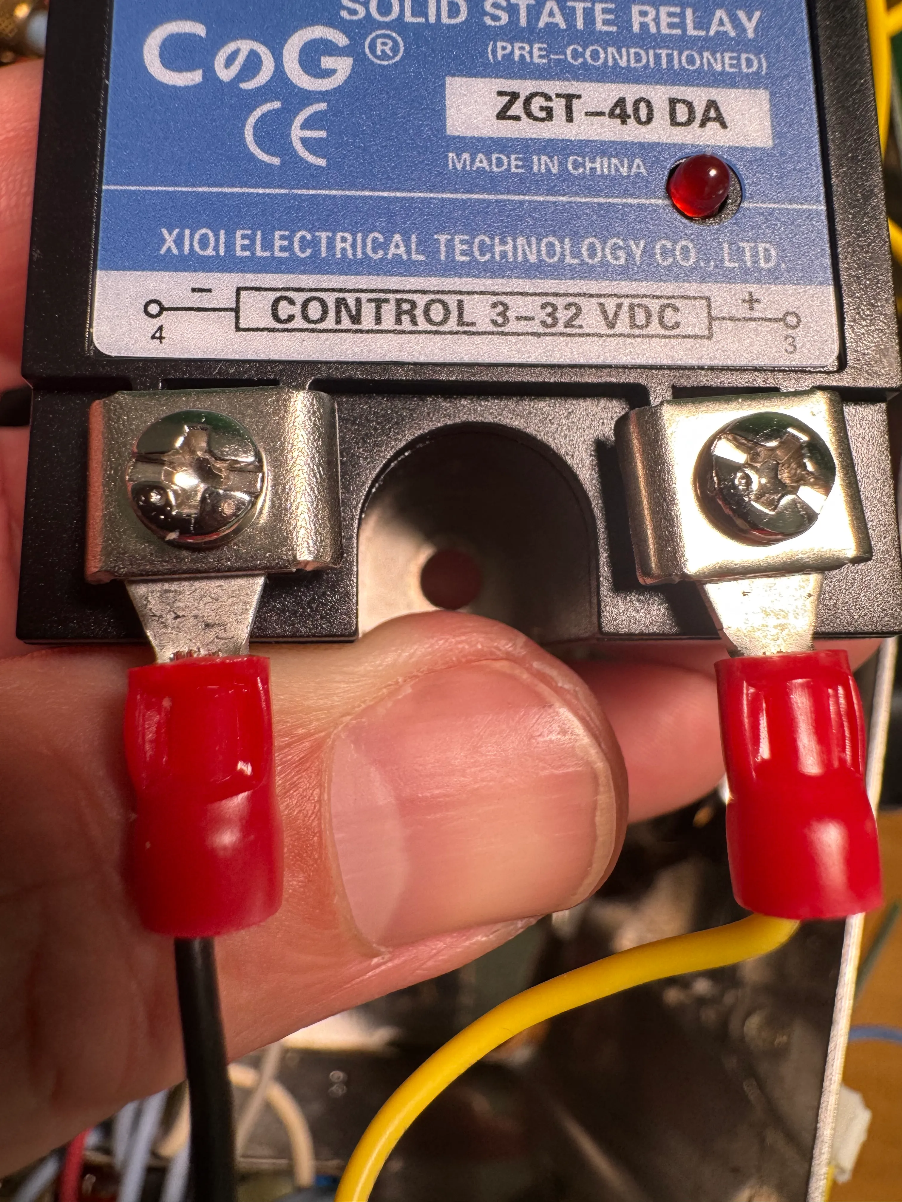
Connect the SSR signal cable to the lower section of the SSR. The black spade connector goes to the ’-’ port. The yellow spade connector goes to ’+’. Fasten the screws of the SSR and put on the transparent cover.
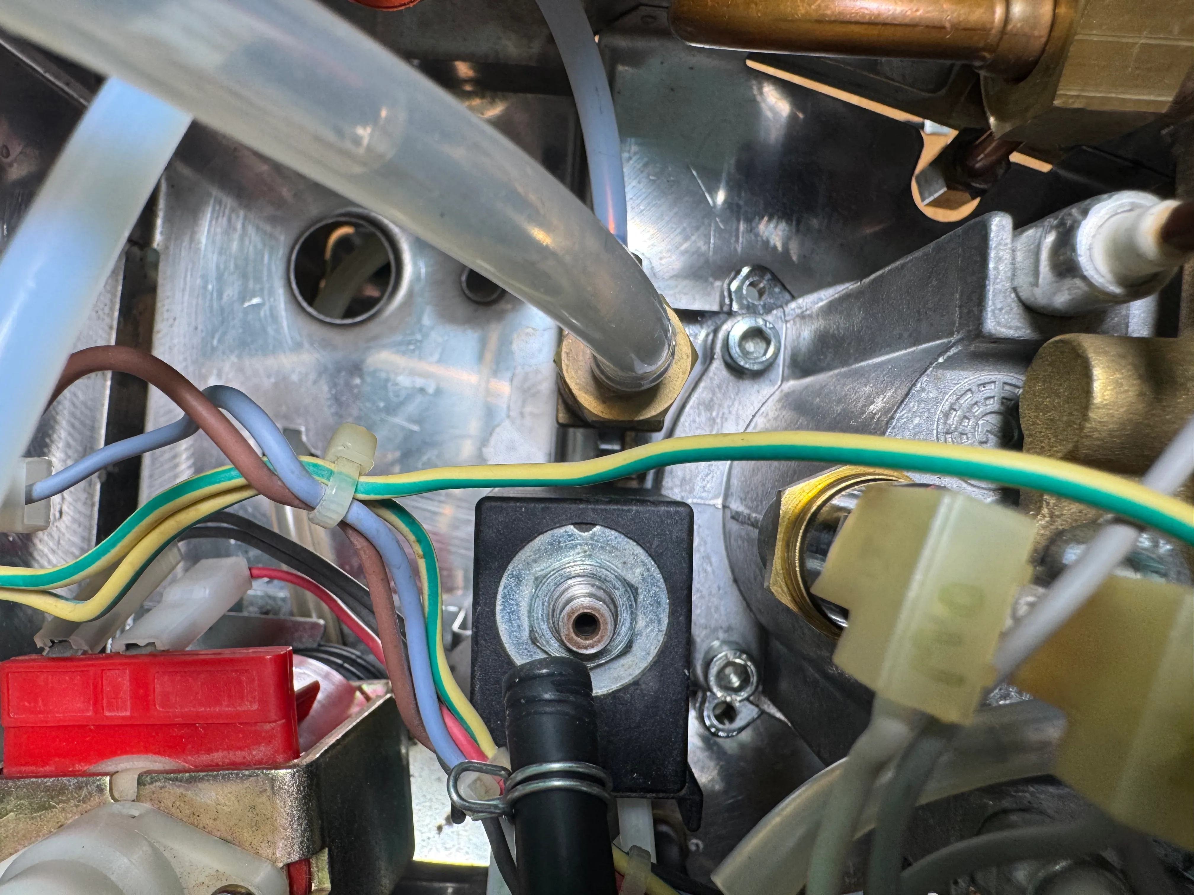
11 Temp sensor
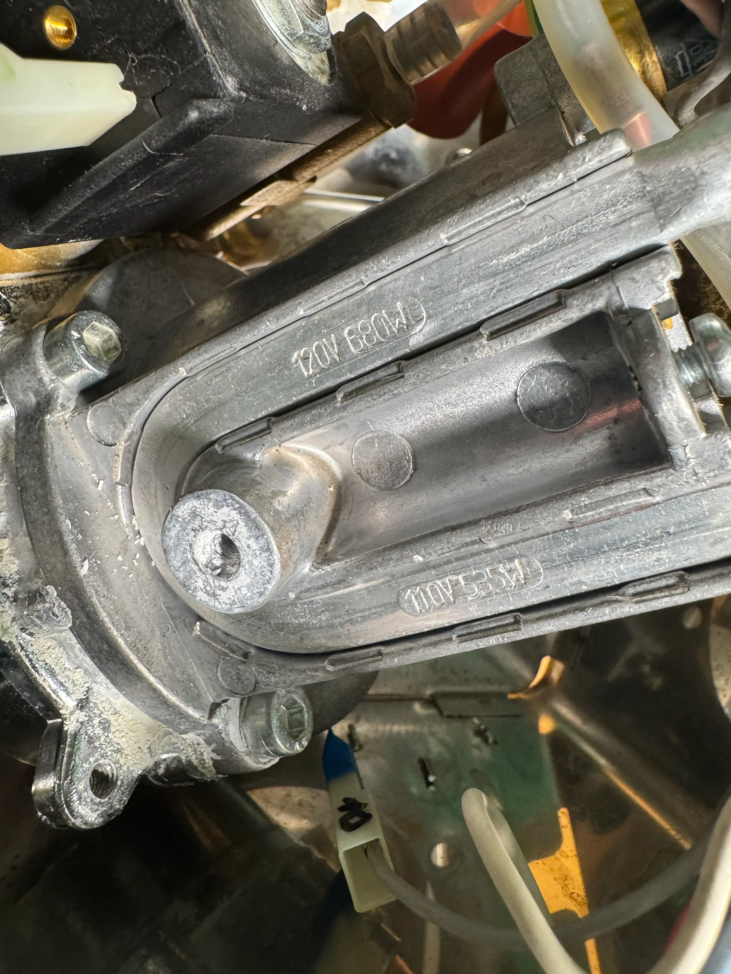
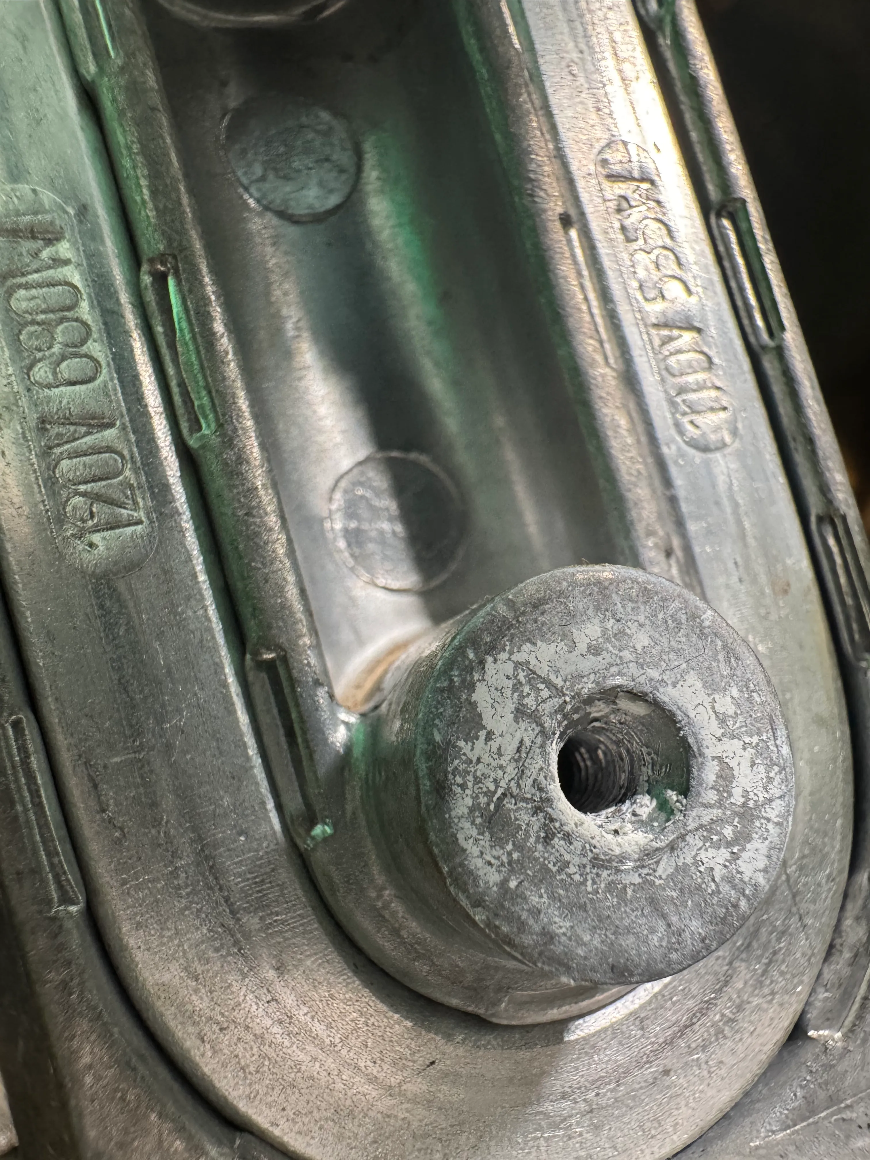
Lift and tilt the boiler to the right towards the steam valve. The screw hole where the brew thermostat used to be is now easily accessible. Make sure the screw hole is free of old thermal paste and gunk.
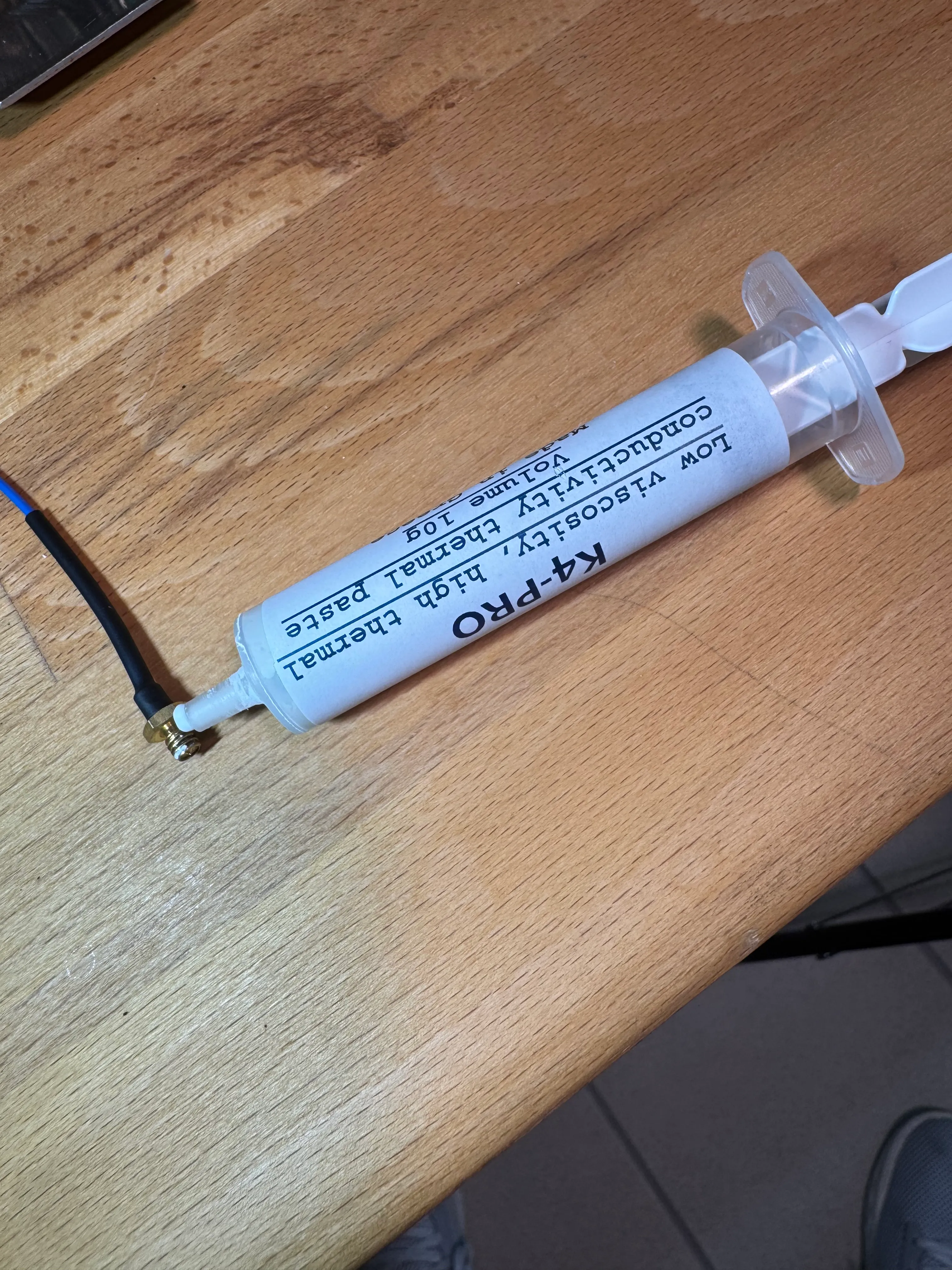
If you have thermal paste available, apply some to the threads and tip of the thermo sensor.
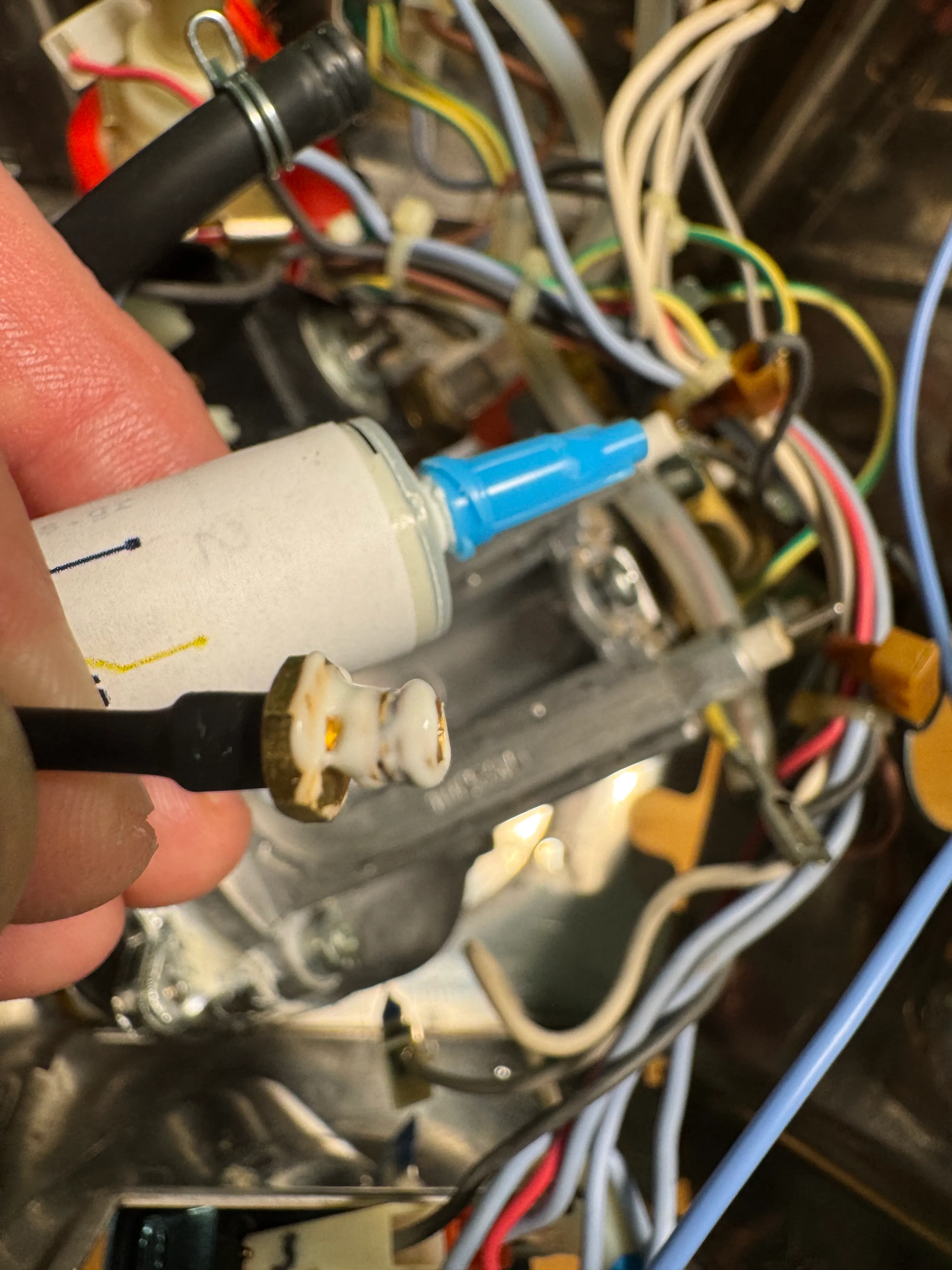
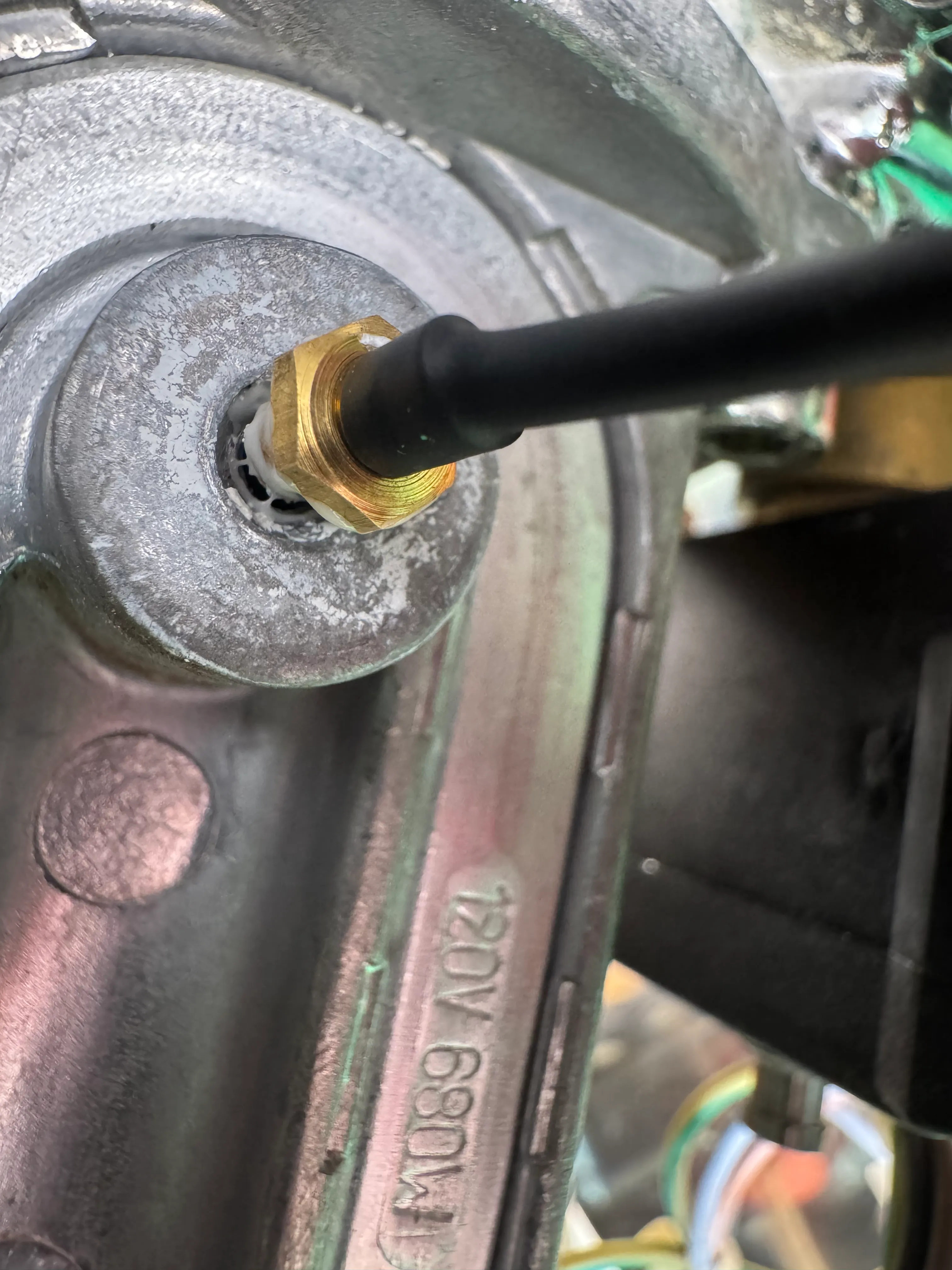
Gently screw the M4 tip of the Thermo sensor into the boiler. Make sure you do not drill or twist the ’-’ and ’+’ ends of the sensor, but move them along with every turn of the M4 end.
12 Pressure sensor and plumbing - only for Gaggimate pro!
12.1 New Plumbing
This section is for the new plumbing, labeled GM-PLUMBING-V1, for the older style with the red tube, please go to 12.2.
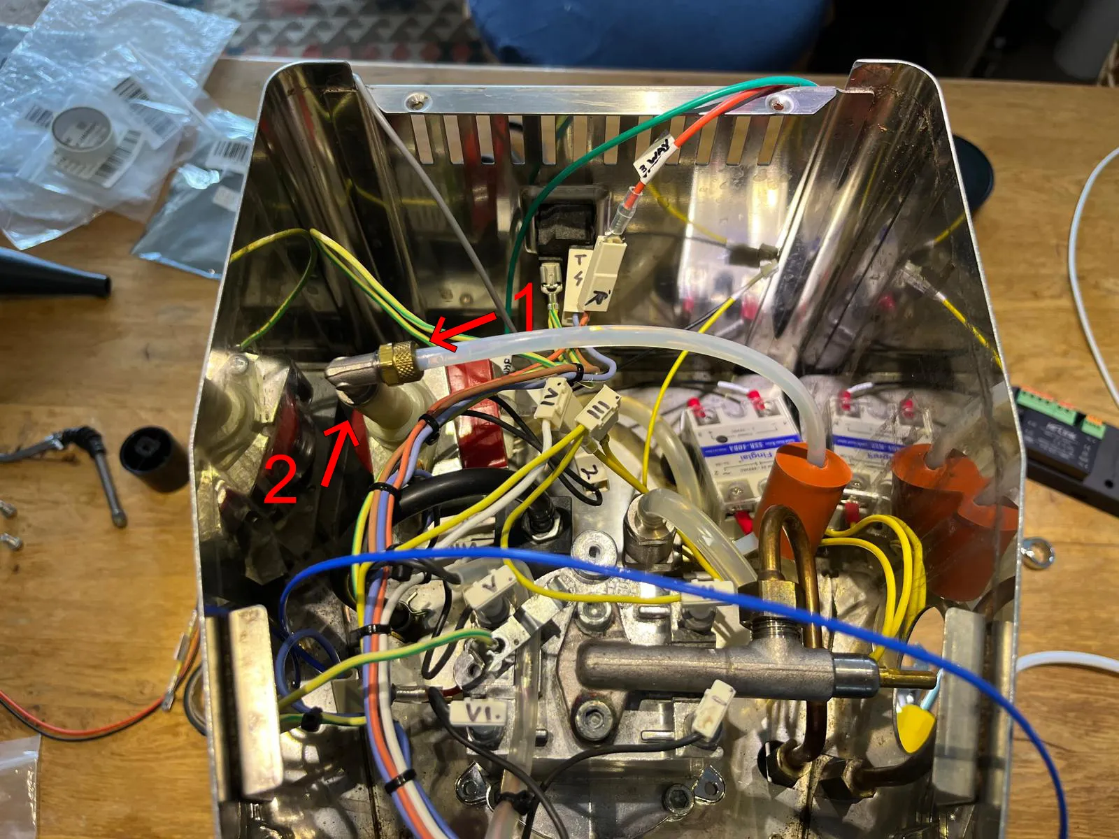
Unscrew the brass nut from the pump fitting (marked 1) and pull off the PTFE hose connected to it. Afterwards, unscrew the whole fitting from the pump (marked 2).
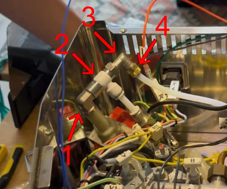
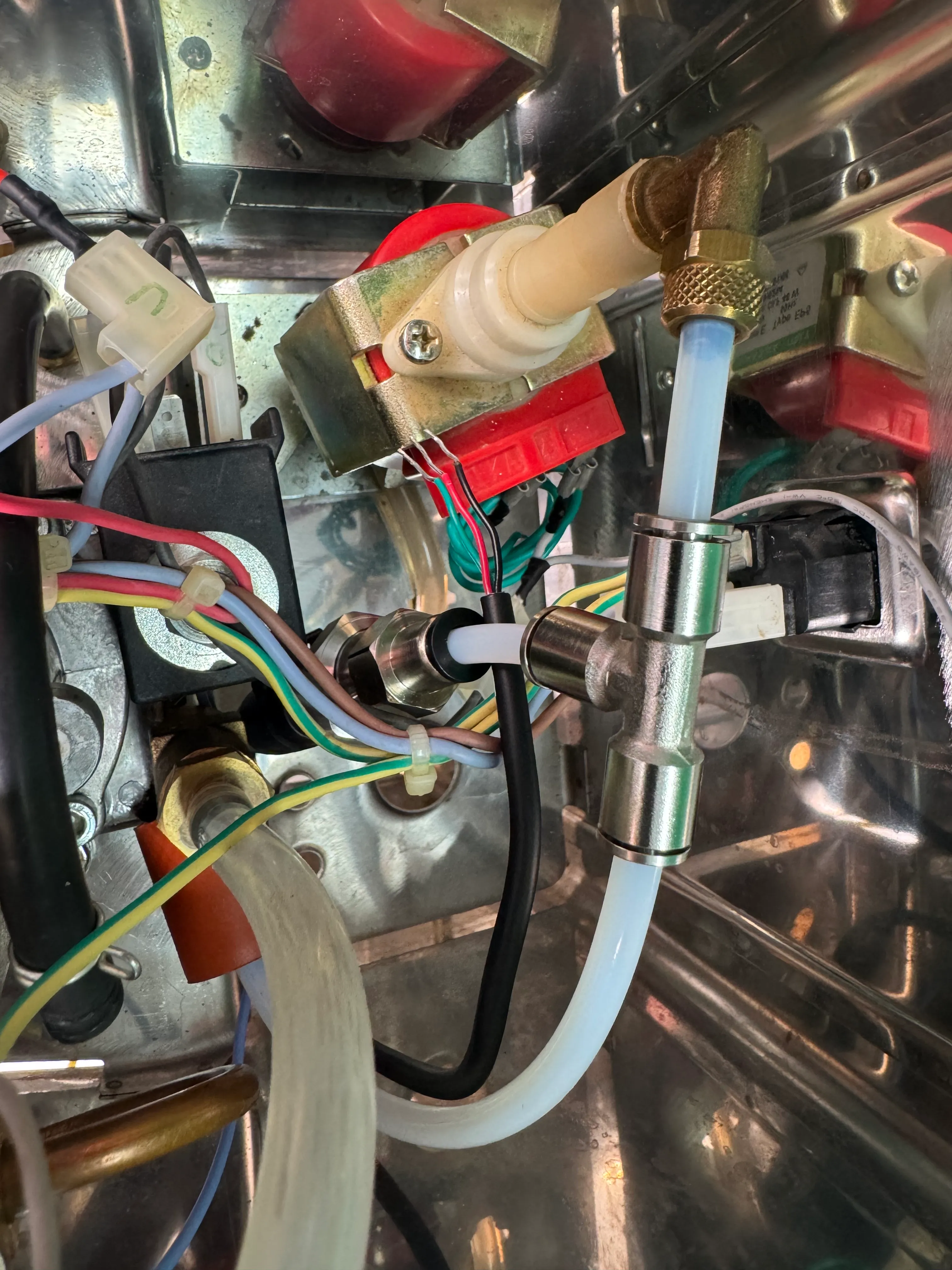
You will now install additional fittings to the pump. Start with the 90 degree elbow fitting (1) and screw that onto the pump. Next install the white T-fitting and tighten (2). Now you install the original fitting back onto the T-fitting (3) and finally push back the hose onto the original fitting and tighten with the brass nut (4).
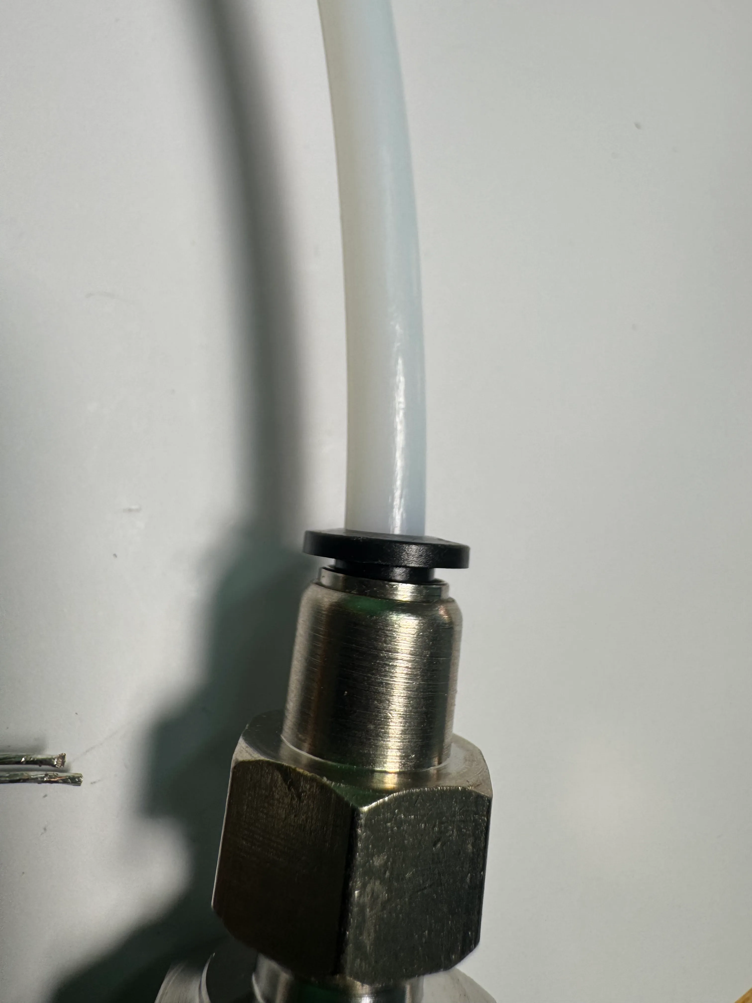
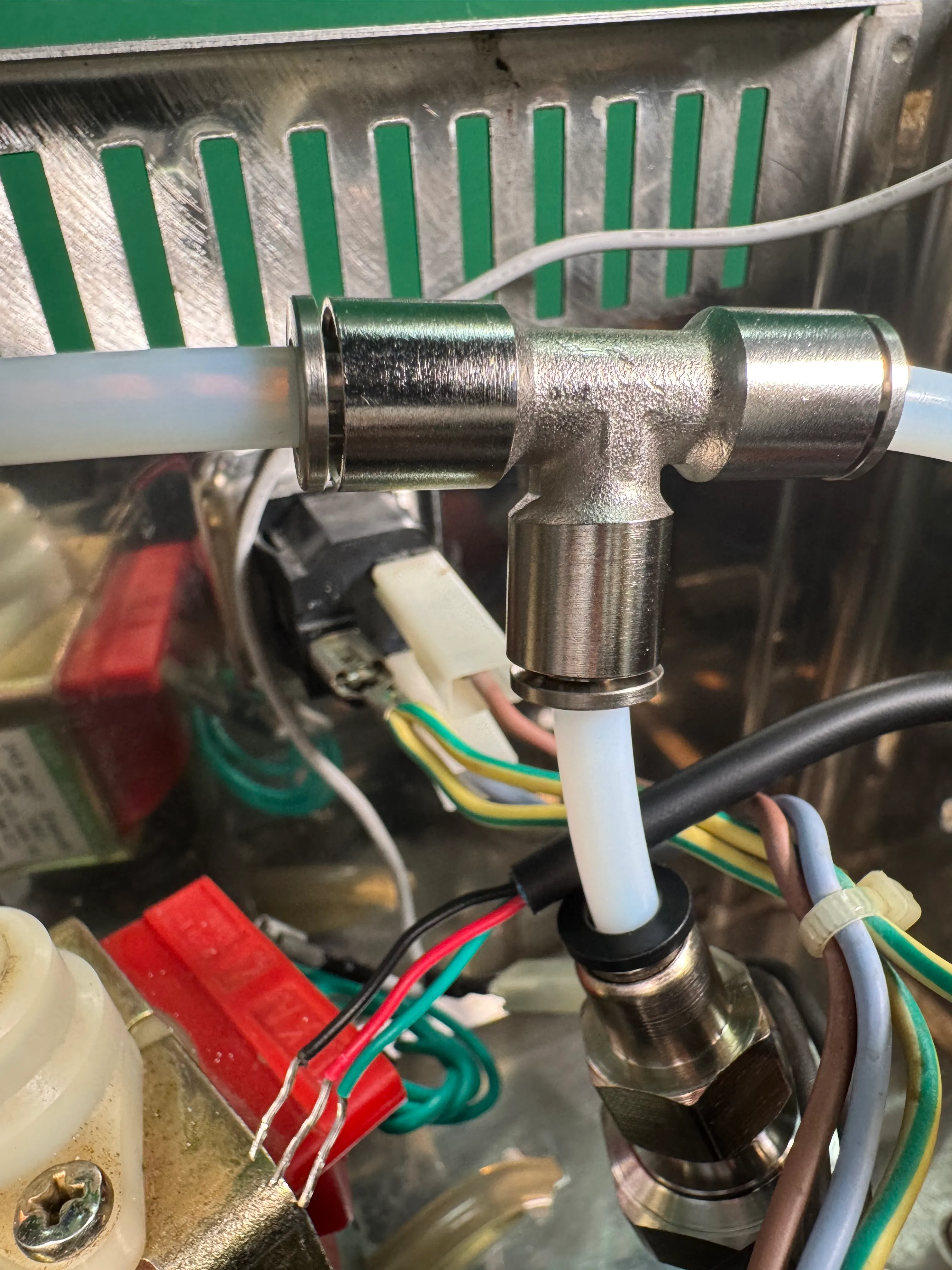
Once you have secure all the fittings, you can assemble the pressure transducer with the straight fitting, cut a piece of PTFE tube to length (so it fits well between pump and 3-Way solenoid) and plug the tube into the white T-fitting and the pressure transducer.
Make sure the tube is pushed in tightly, otherwise leaks could appear.
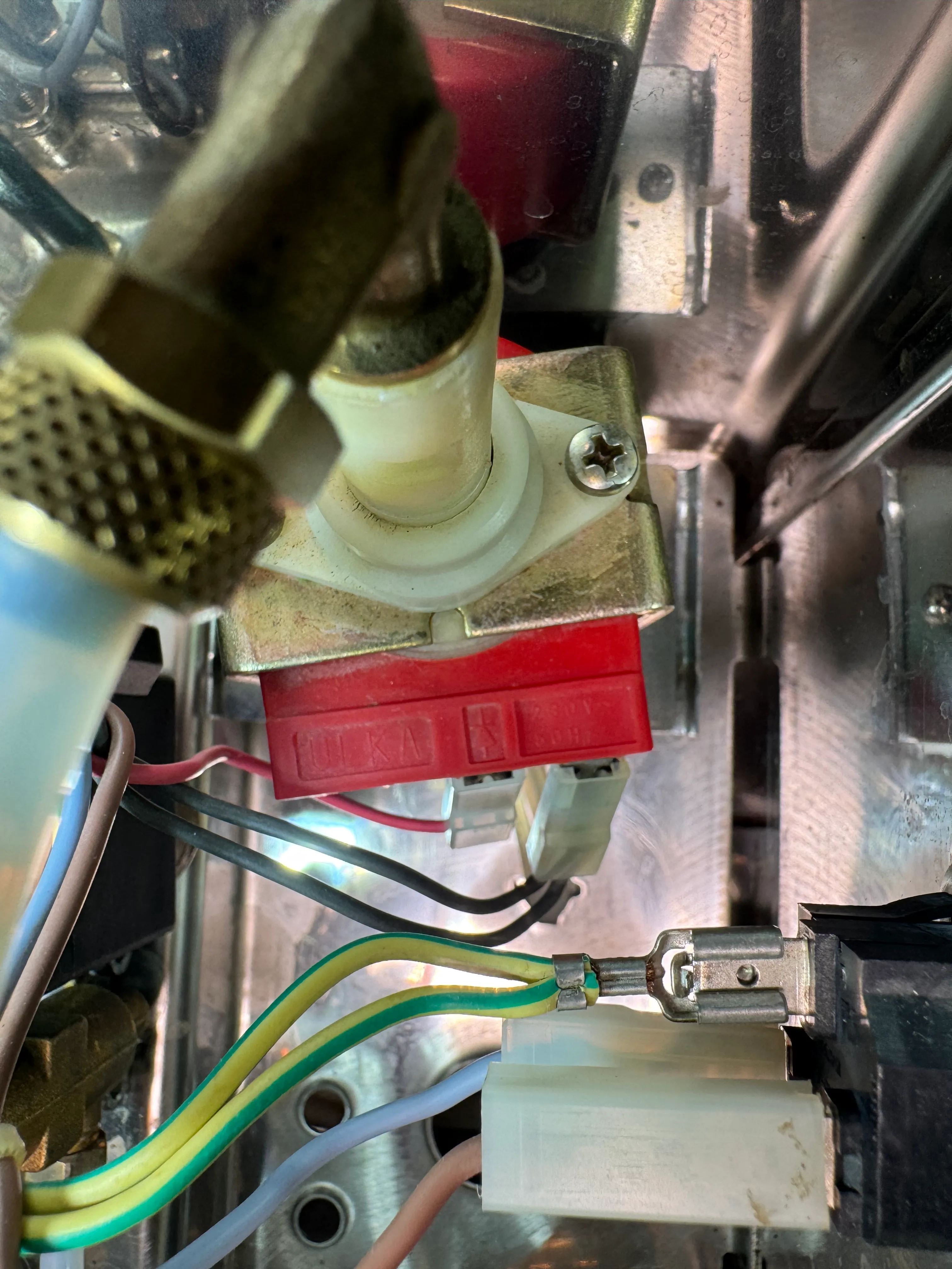
12.2 Old Plumbing
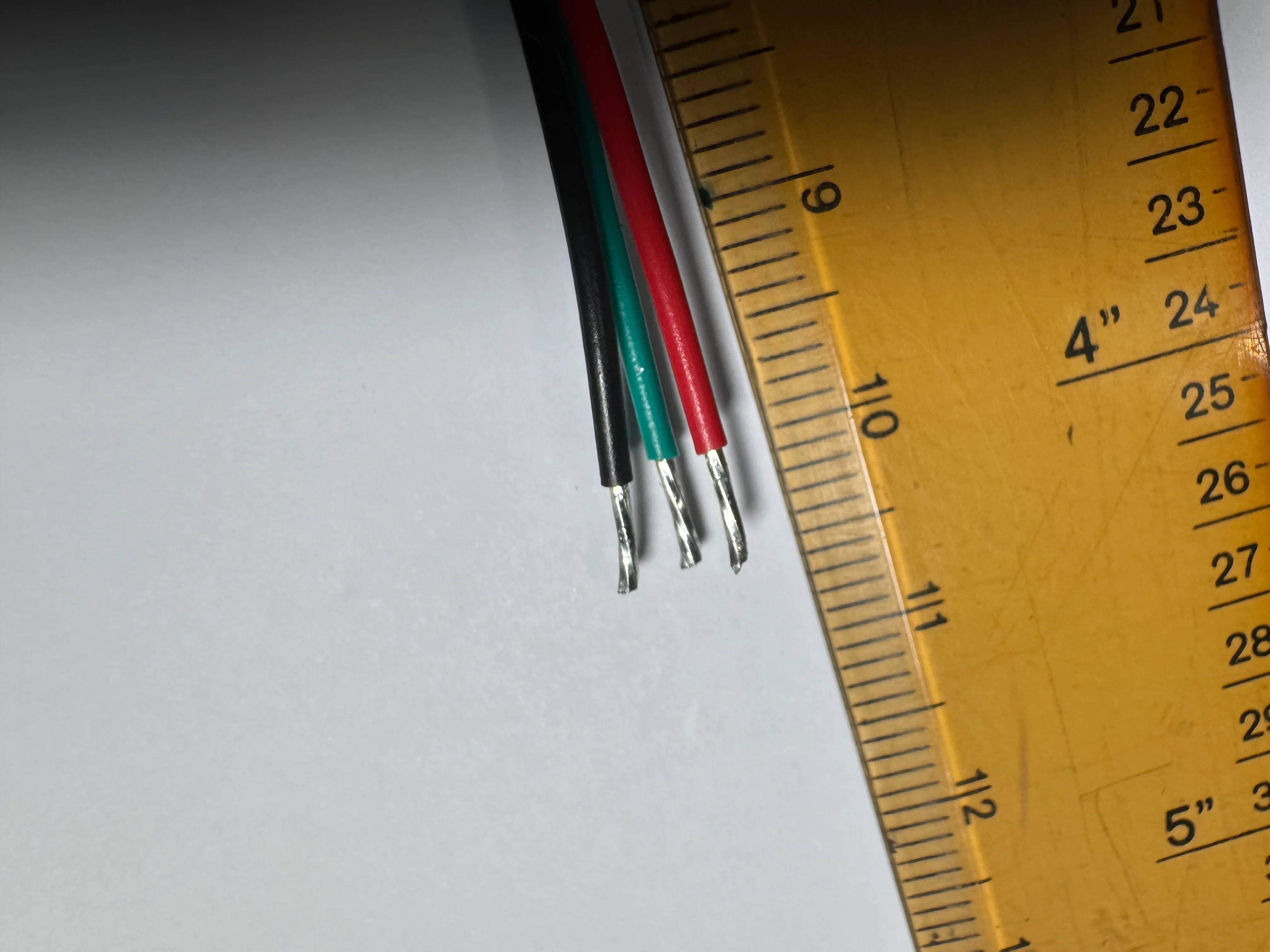
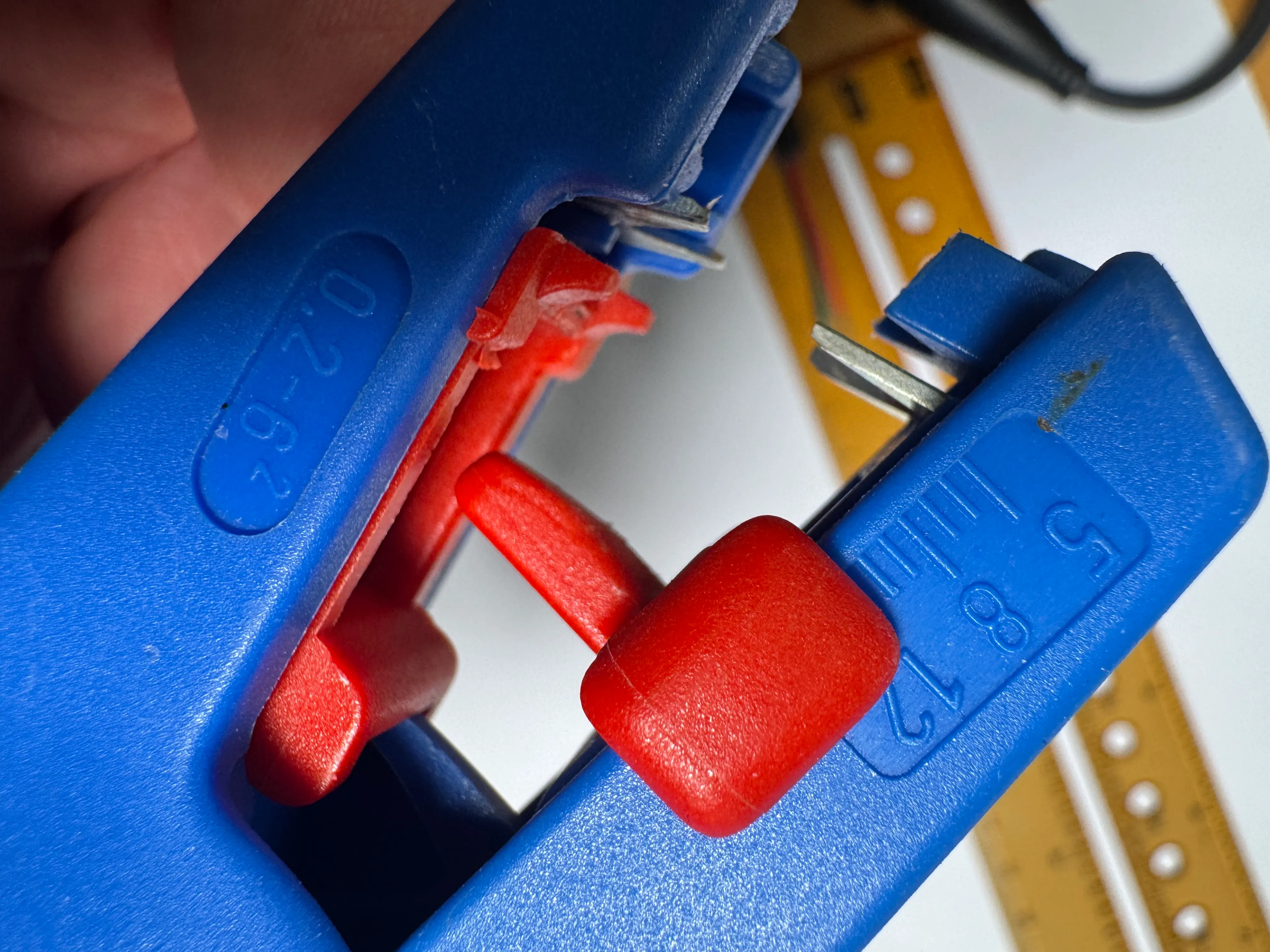
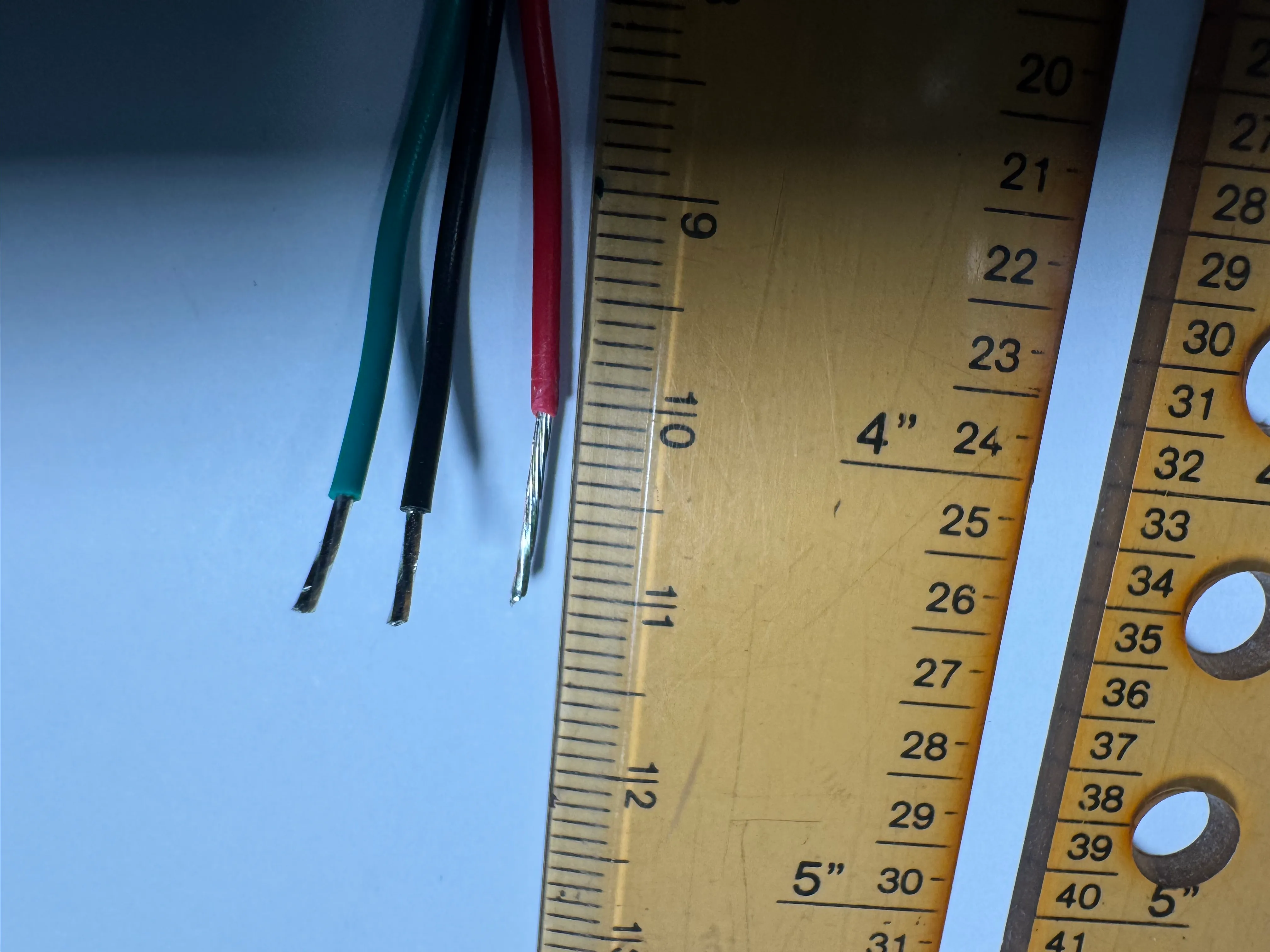
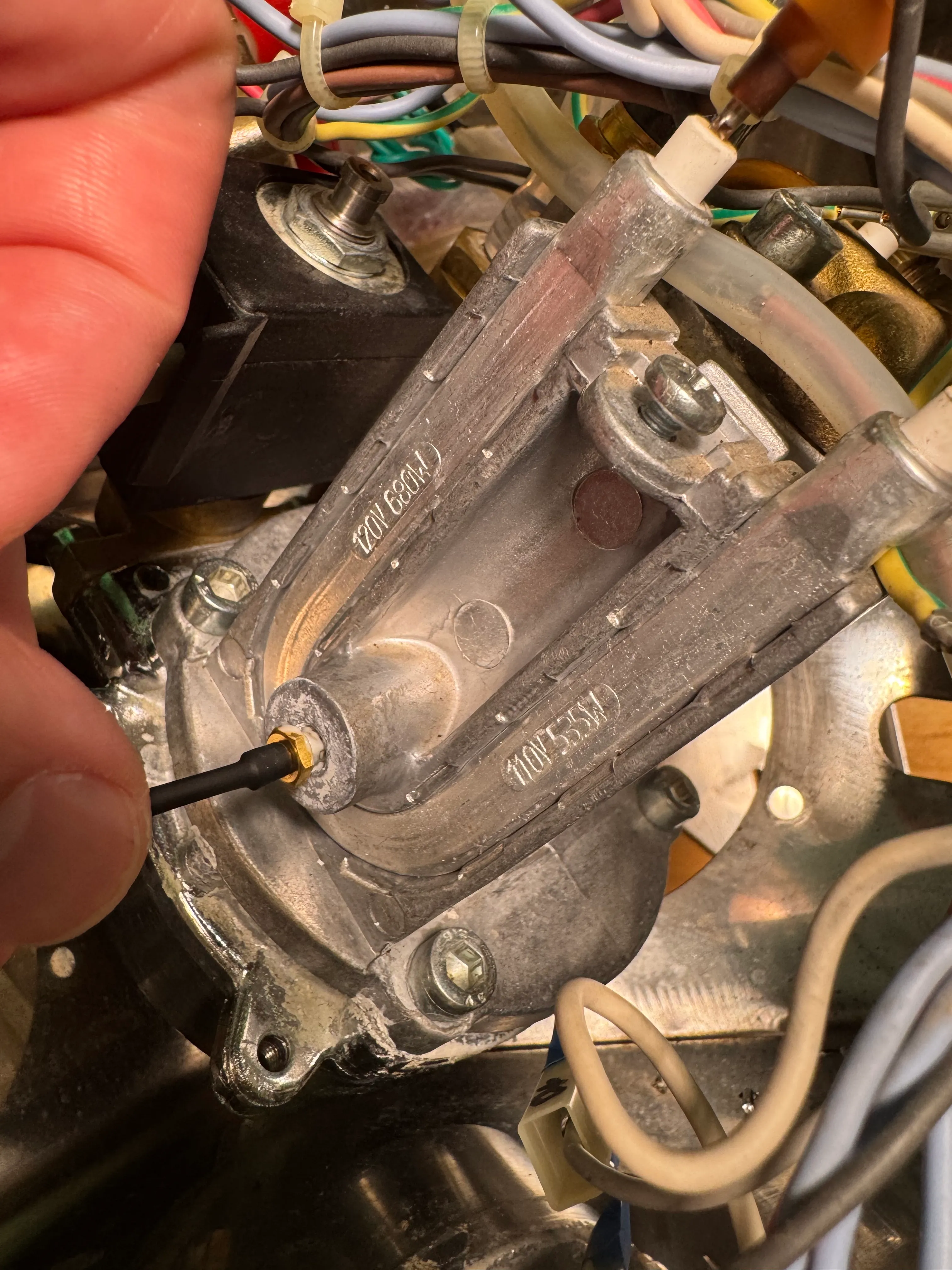
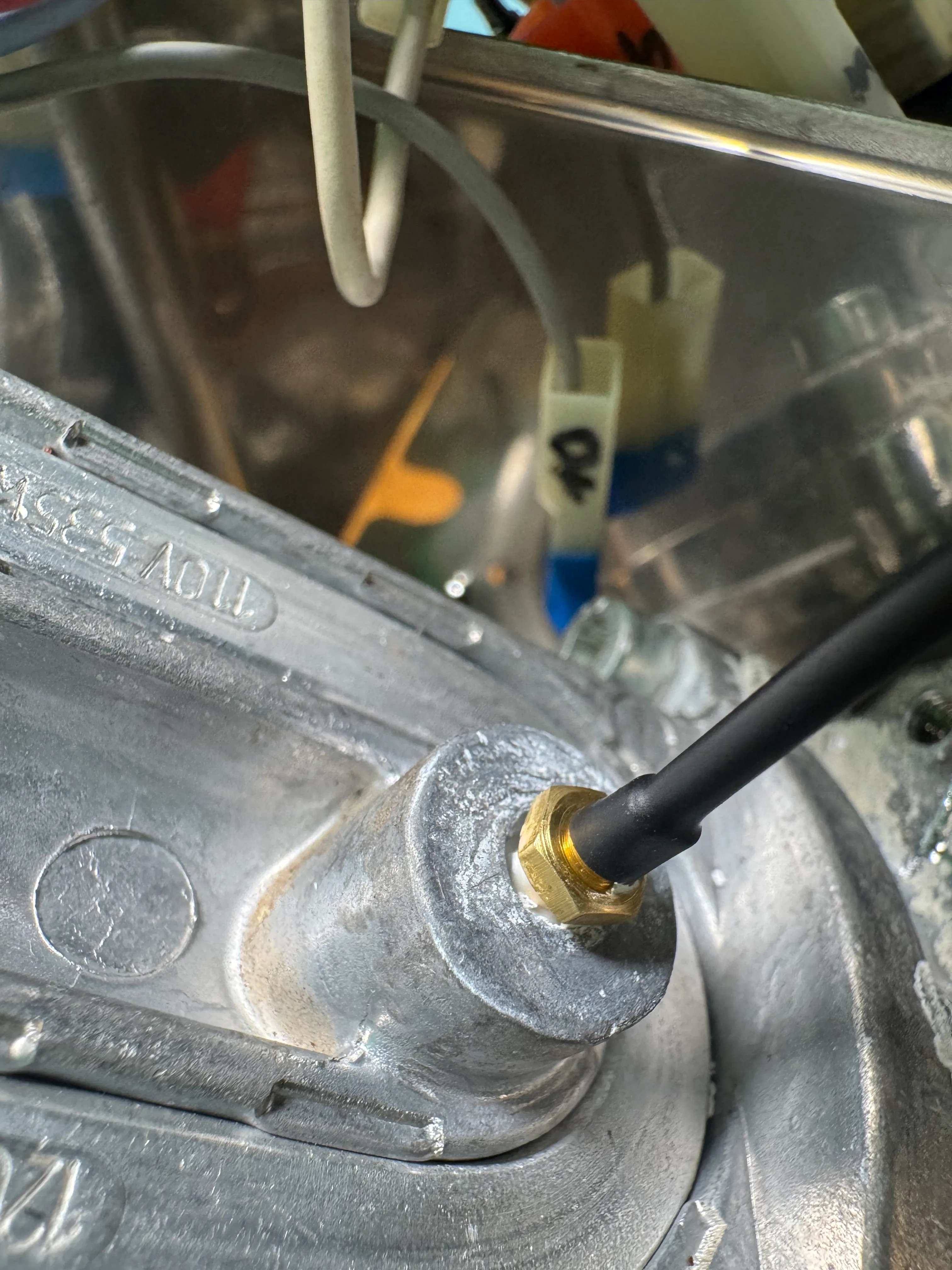
Measure the wire ends of the pressure sensor. They should have an un-insulated length of 11mm. If needed, strip the insulation accordingly.
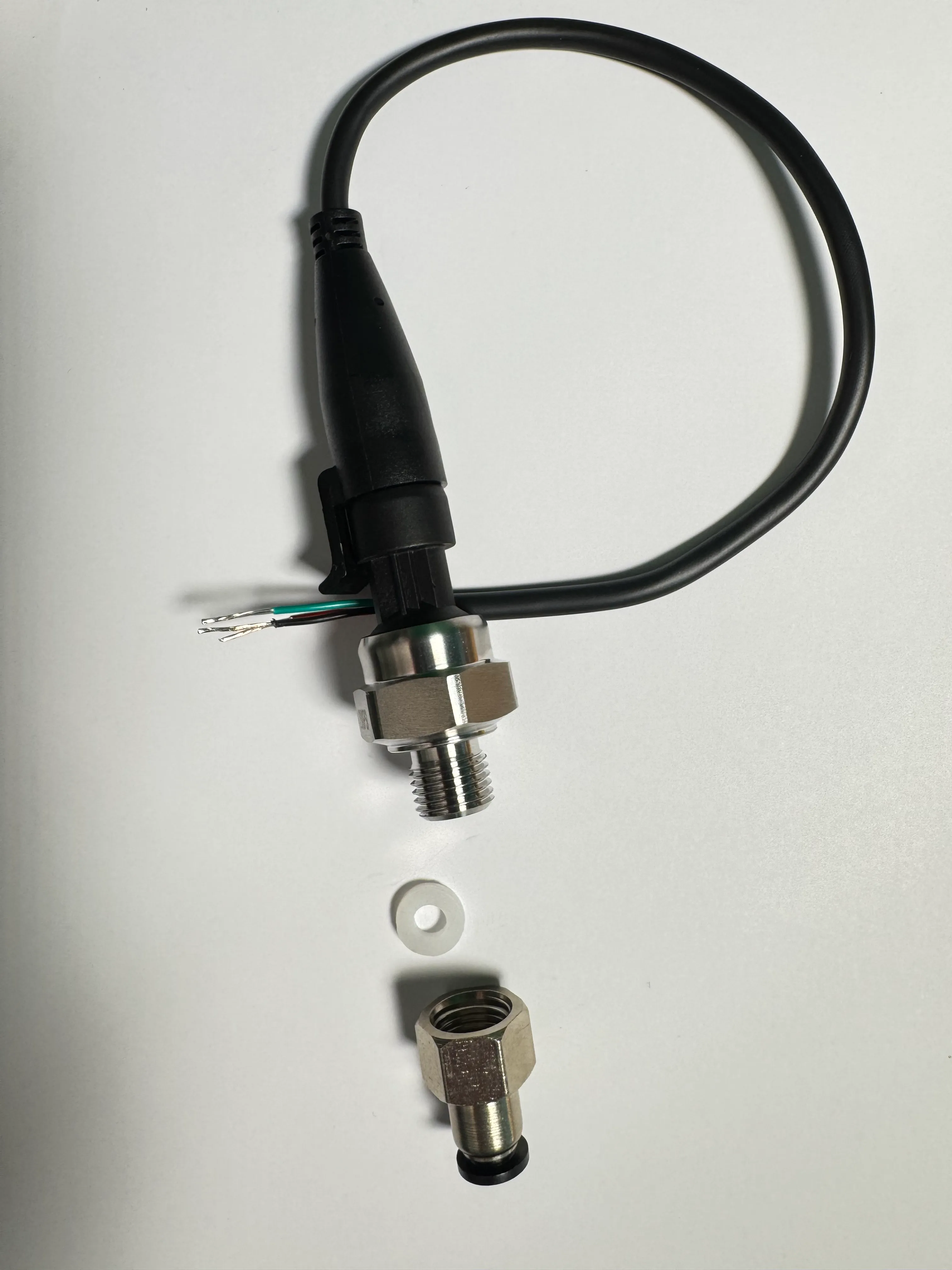
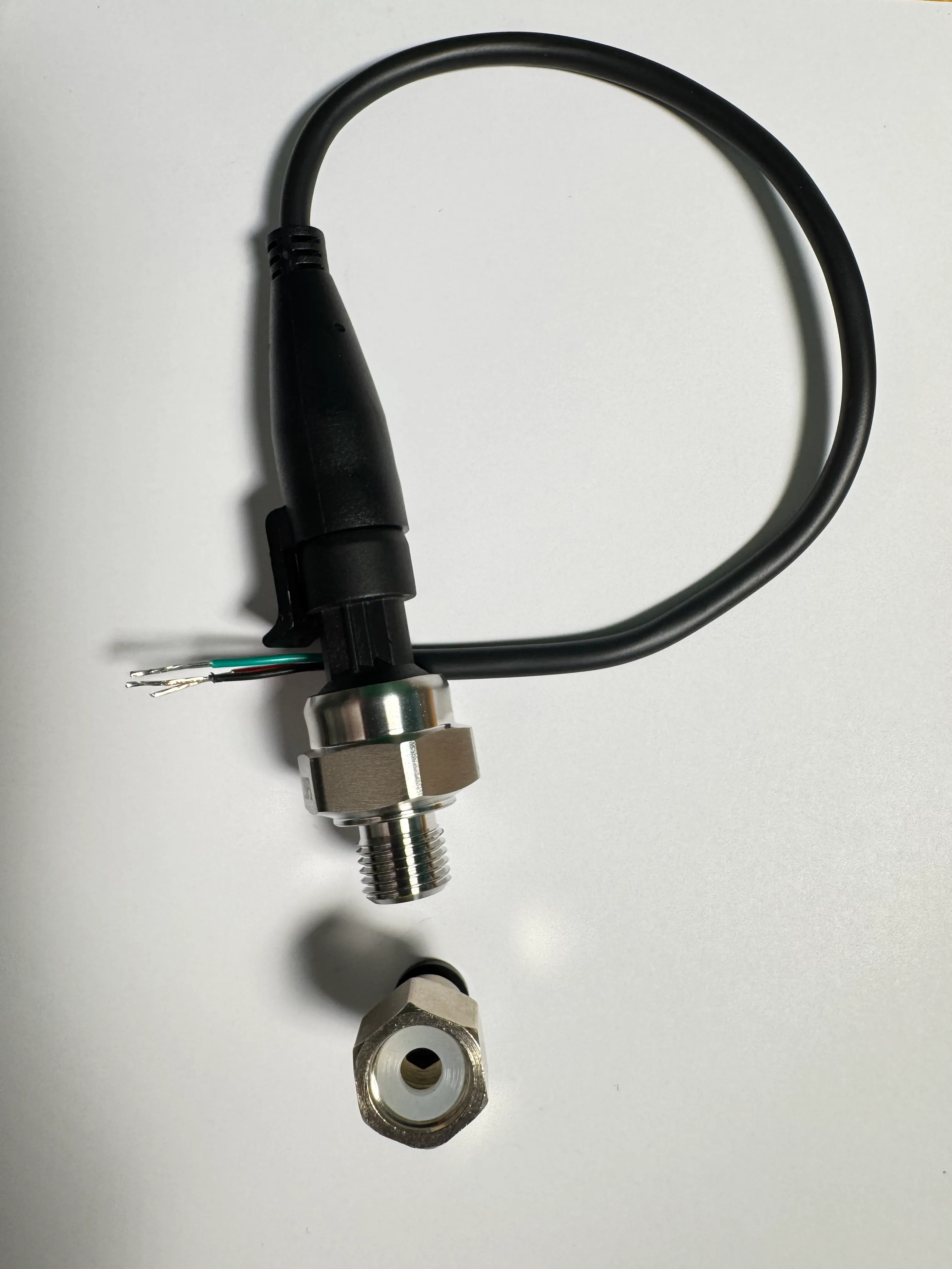
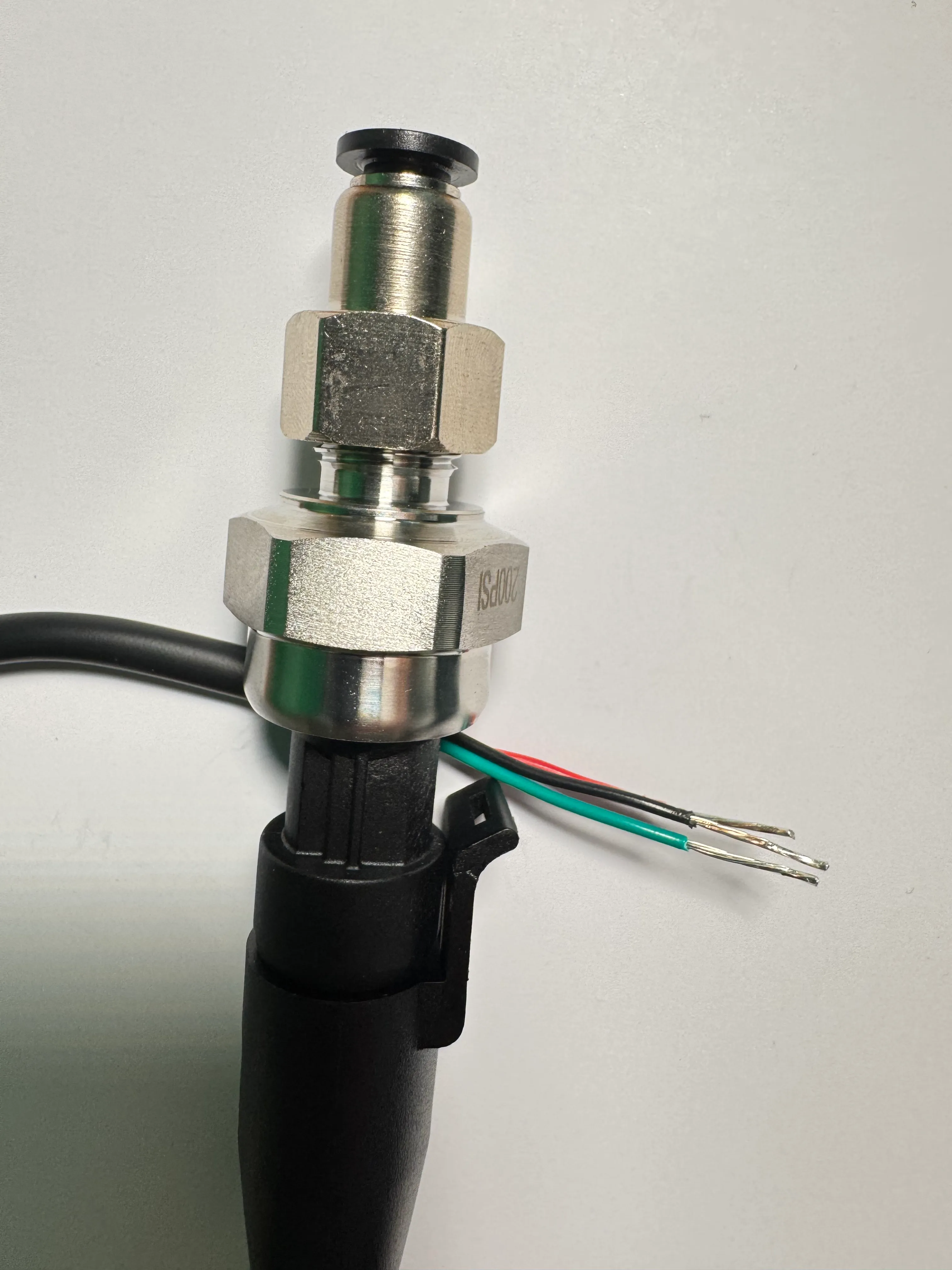
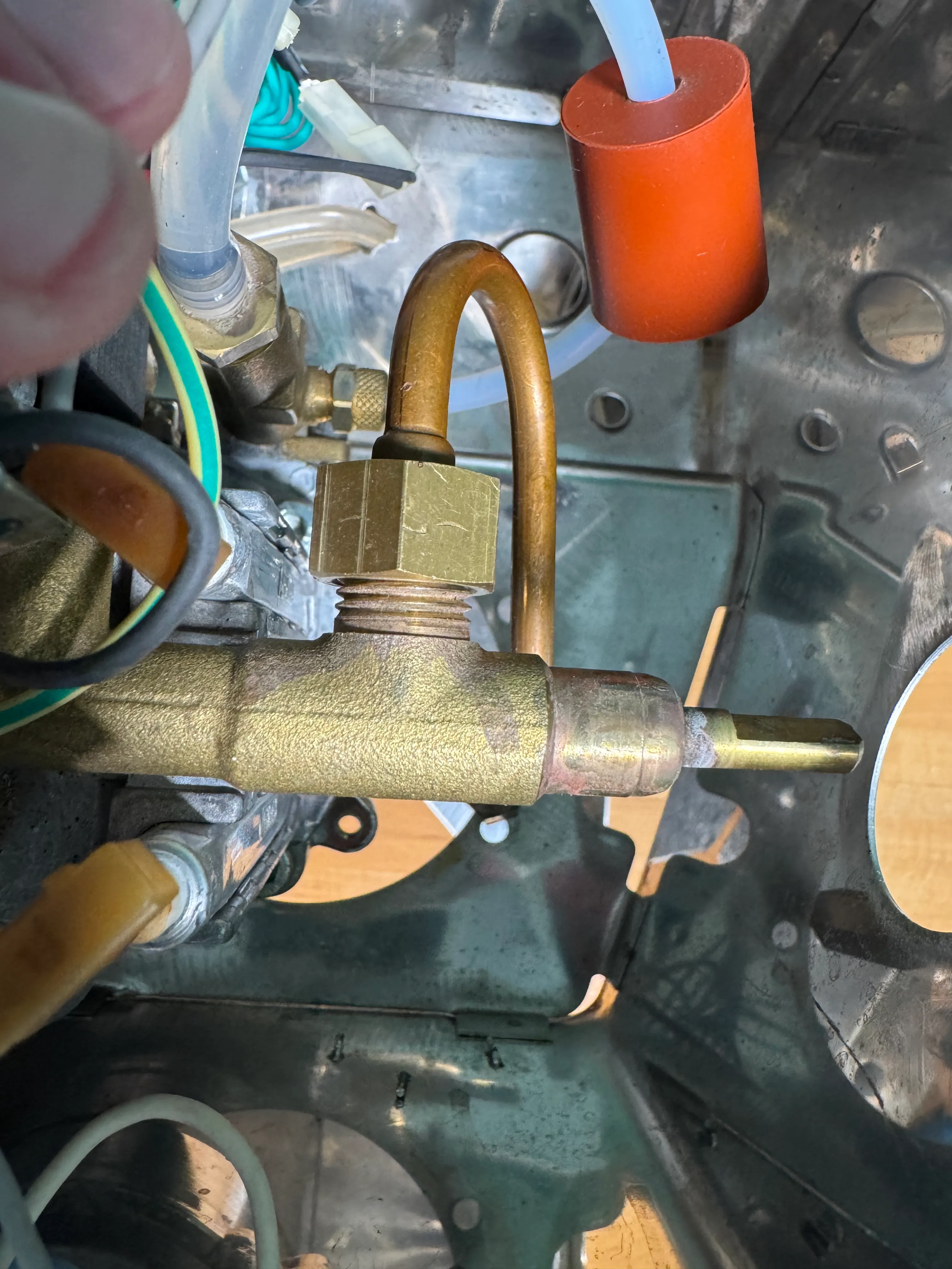
Assemble the pressure sensor, silicone gasket and quick-connect nut. If needed, strip the insulation accordingly.
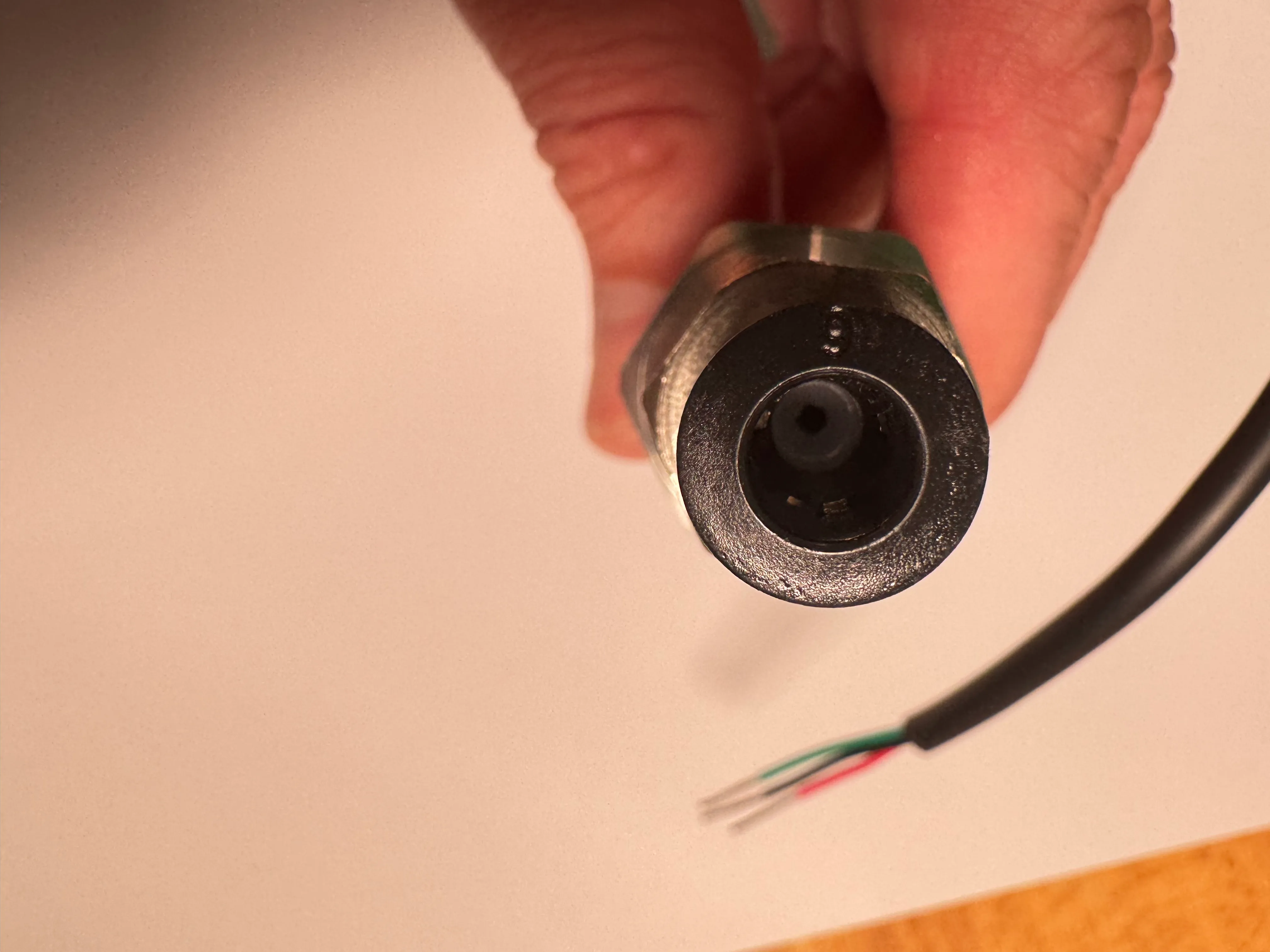
Fasten only hand-tight. Make sure the gasket is plain, not squeezed and the center hole is free.
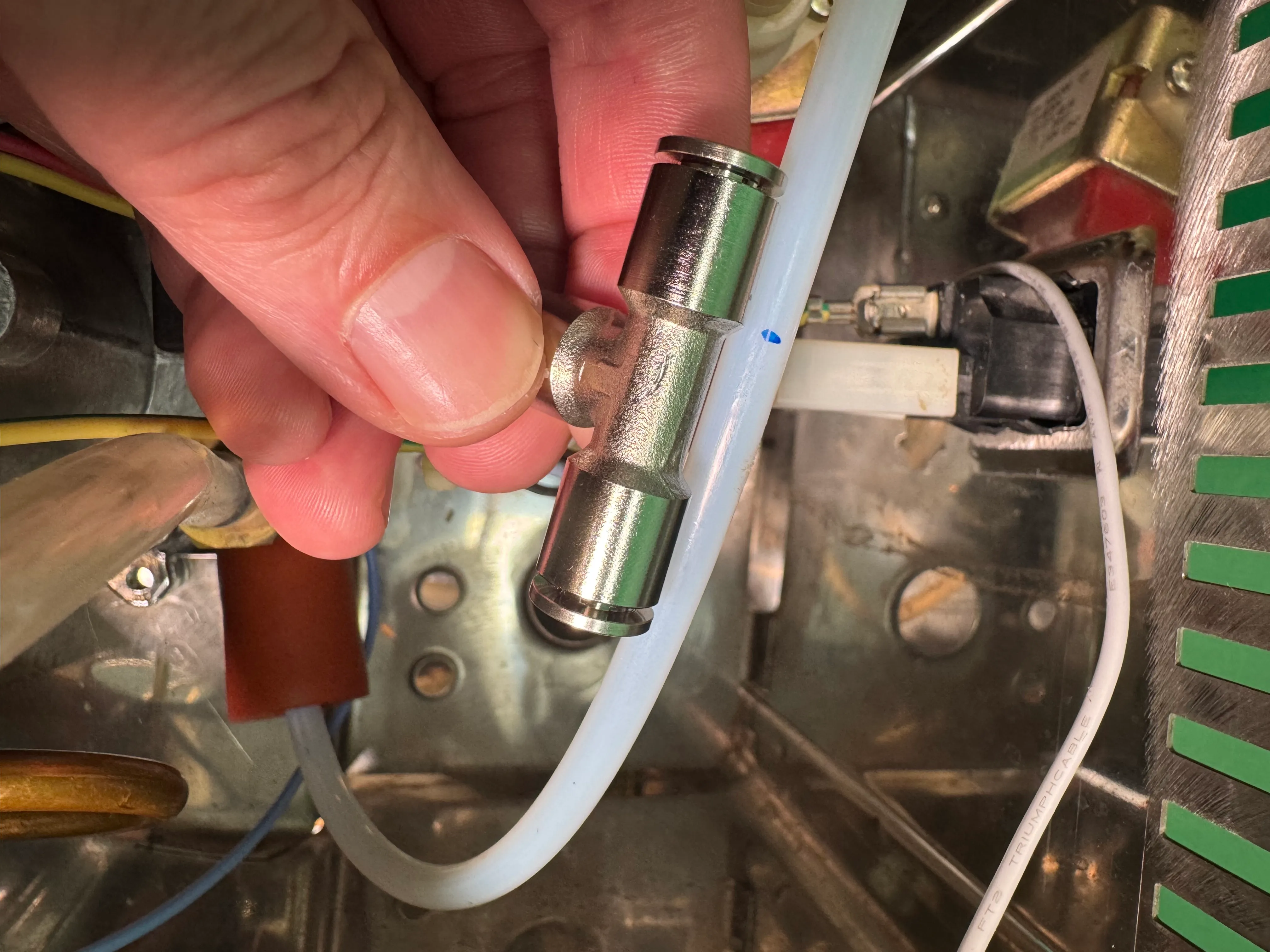
Take the 3-way T-connector and find a good spot between the pump outlet and the 3-way solenoid to install the T-connector. Mark and cut with a fresh blade.
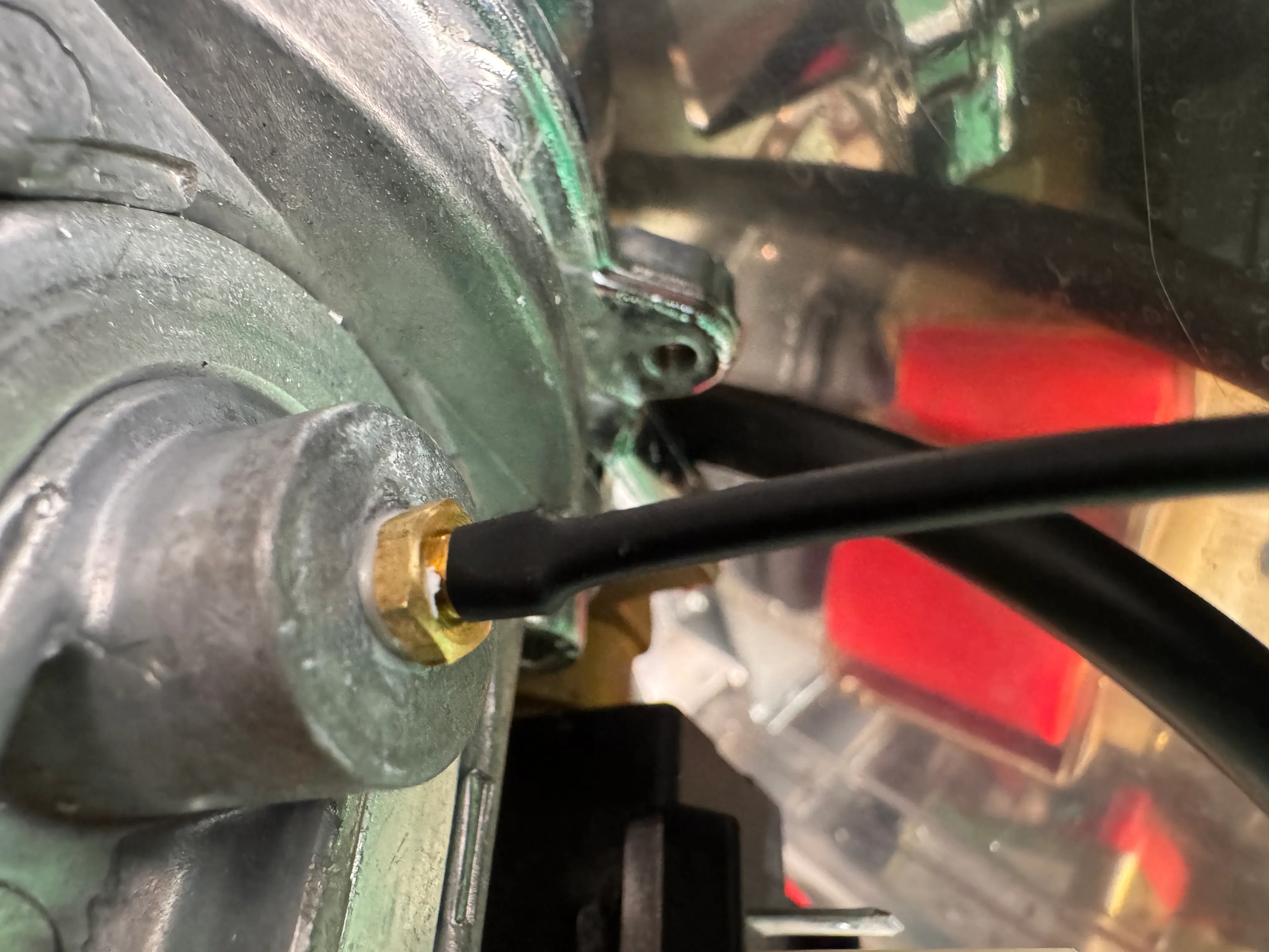
Cut a piece of the supplied tube and firmly push it into the connector of the pressure sensor.
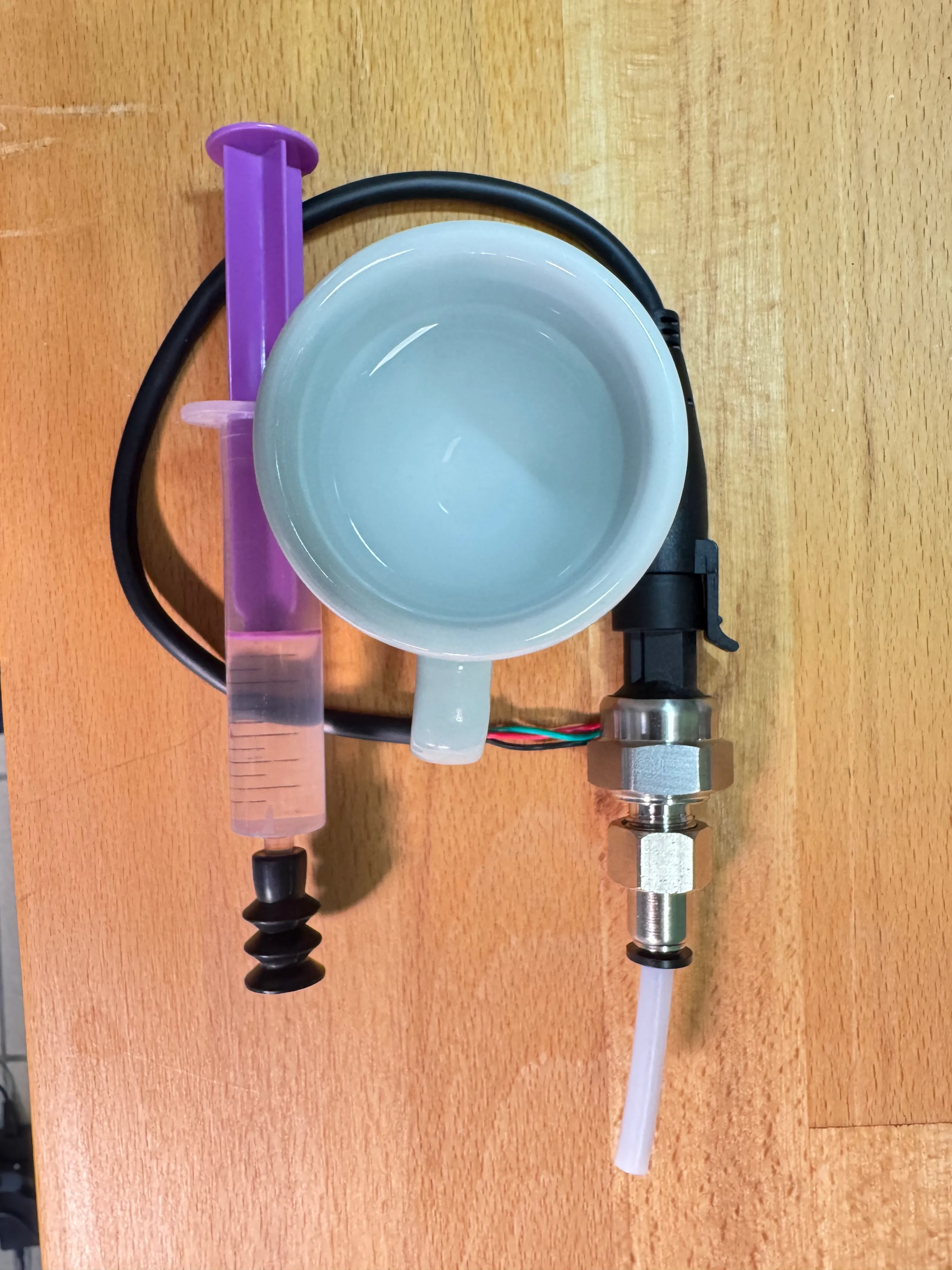
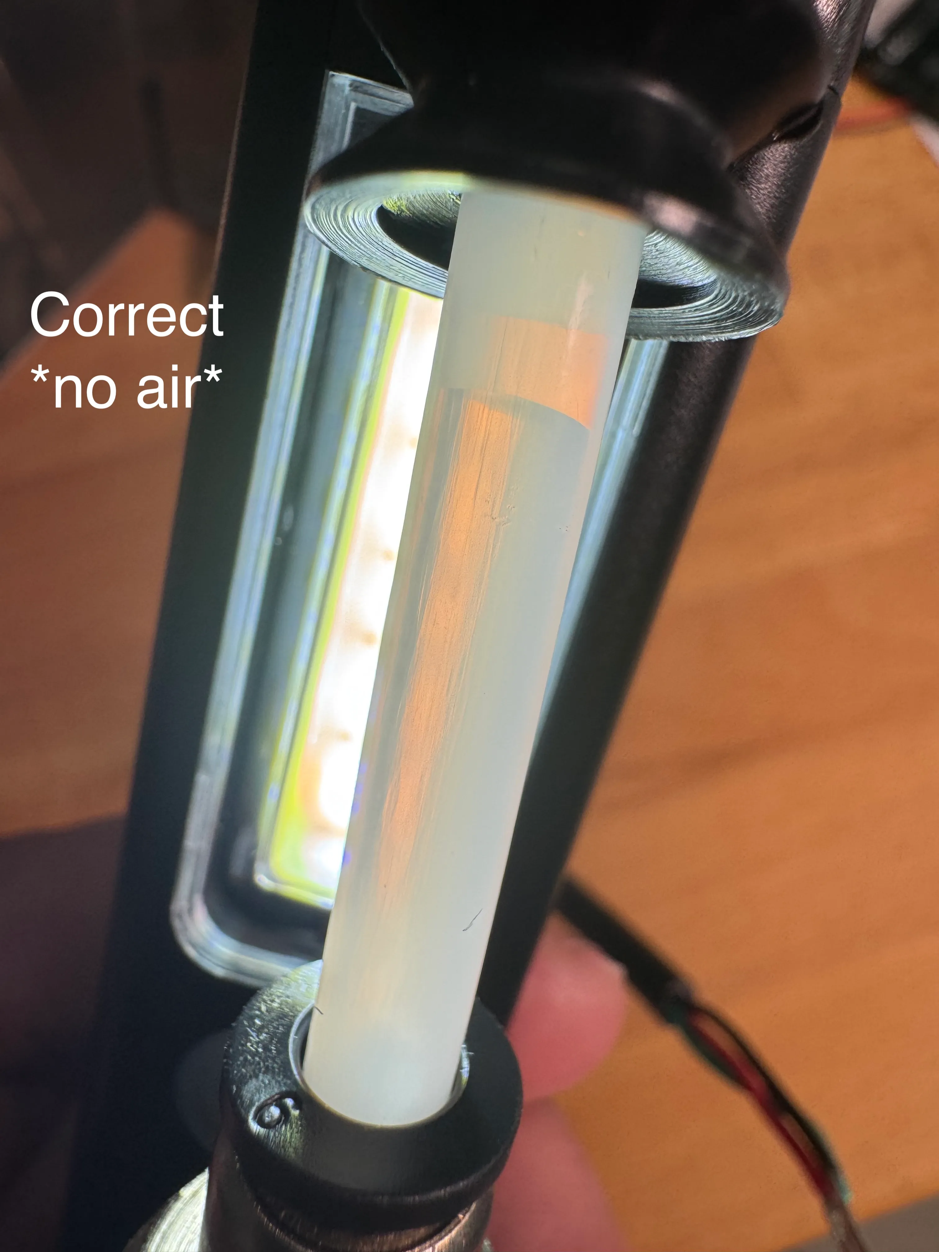
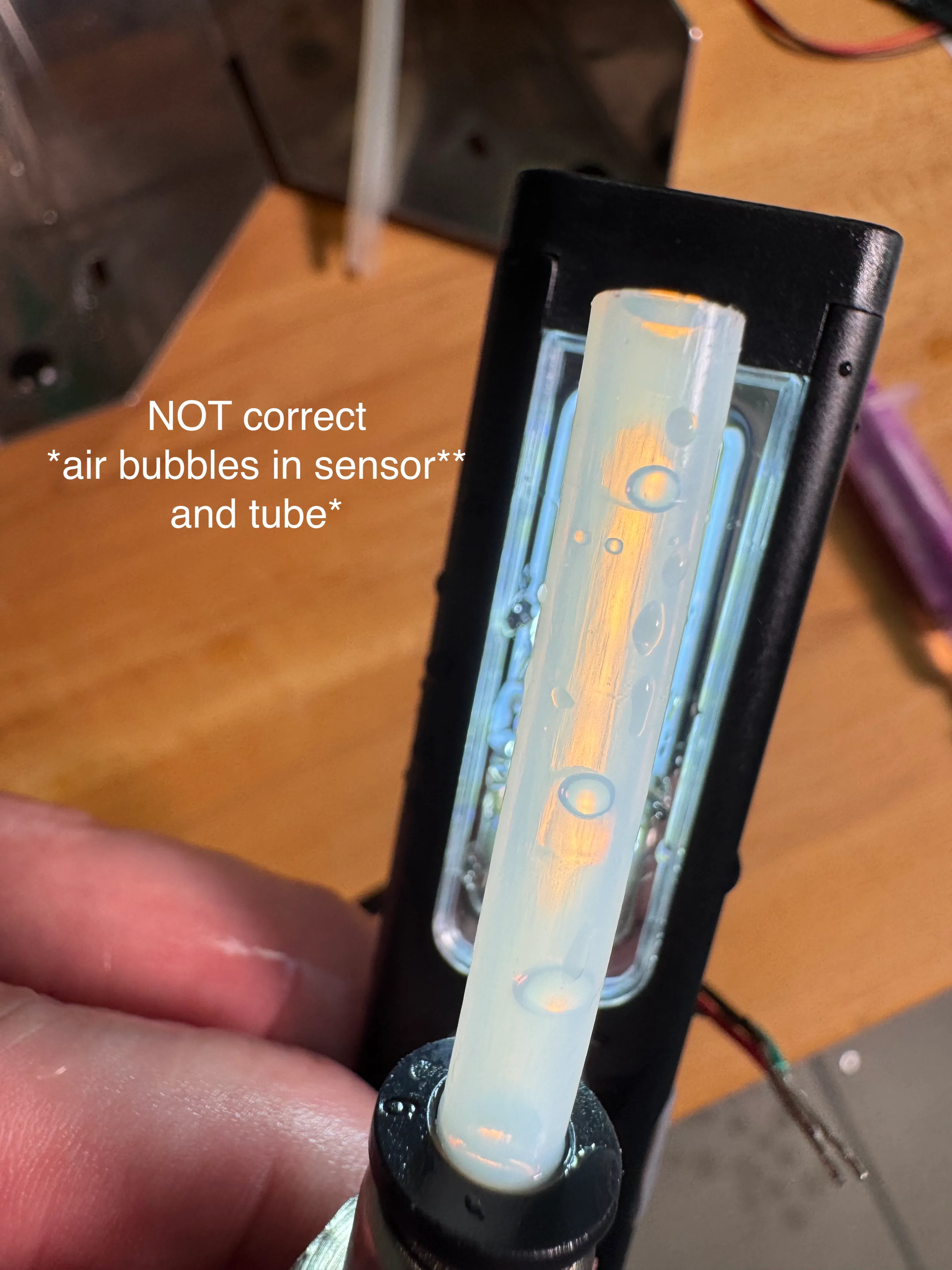
Prefill with water. Either use a syringe or submerge. Make sure there are no bubbles or air in the sensor.
Install the pressure sensor between the pump and the 3-way solenoid.
13 Screen wiring
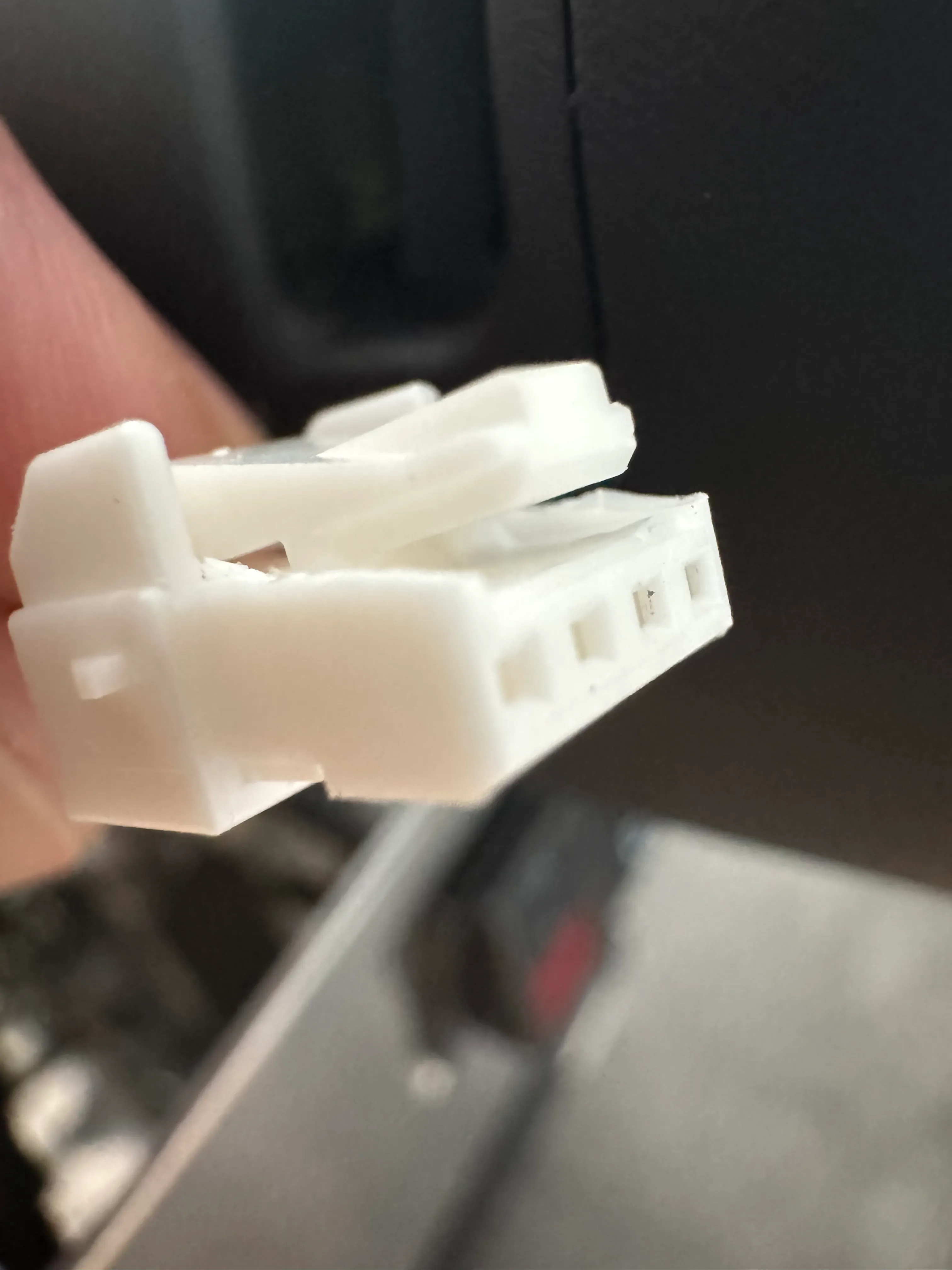
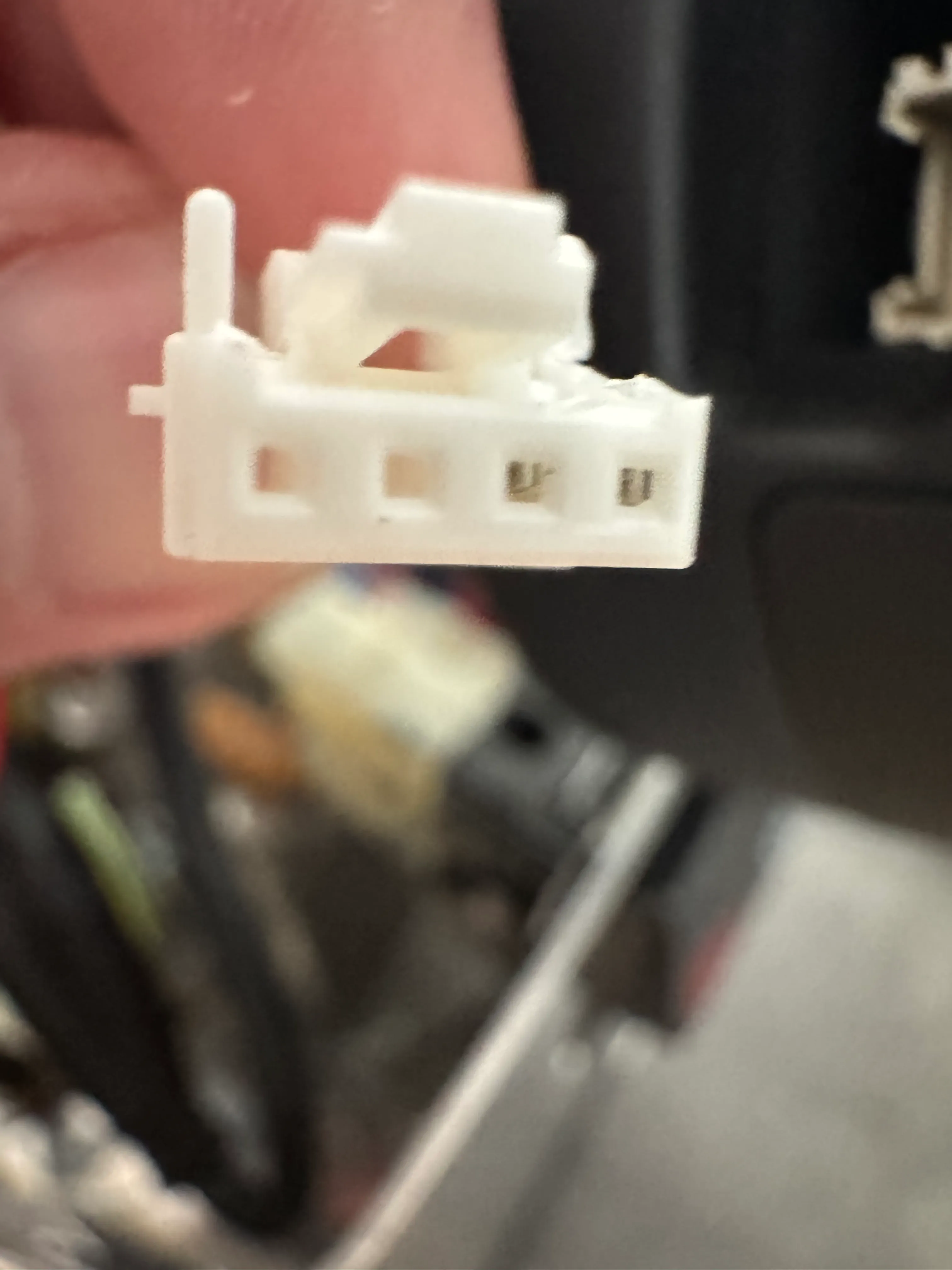
Use the Screen power cable and plug it into the side of the screen. You may have to trim the edges of the connector of the screen side of the cable in order to plug it in smoothly.
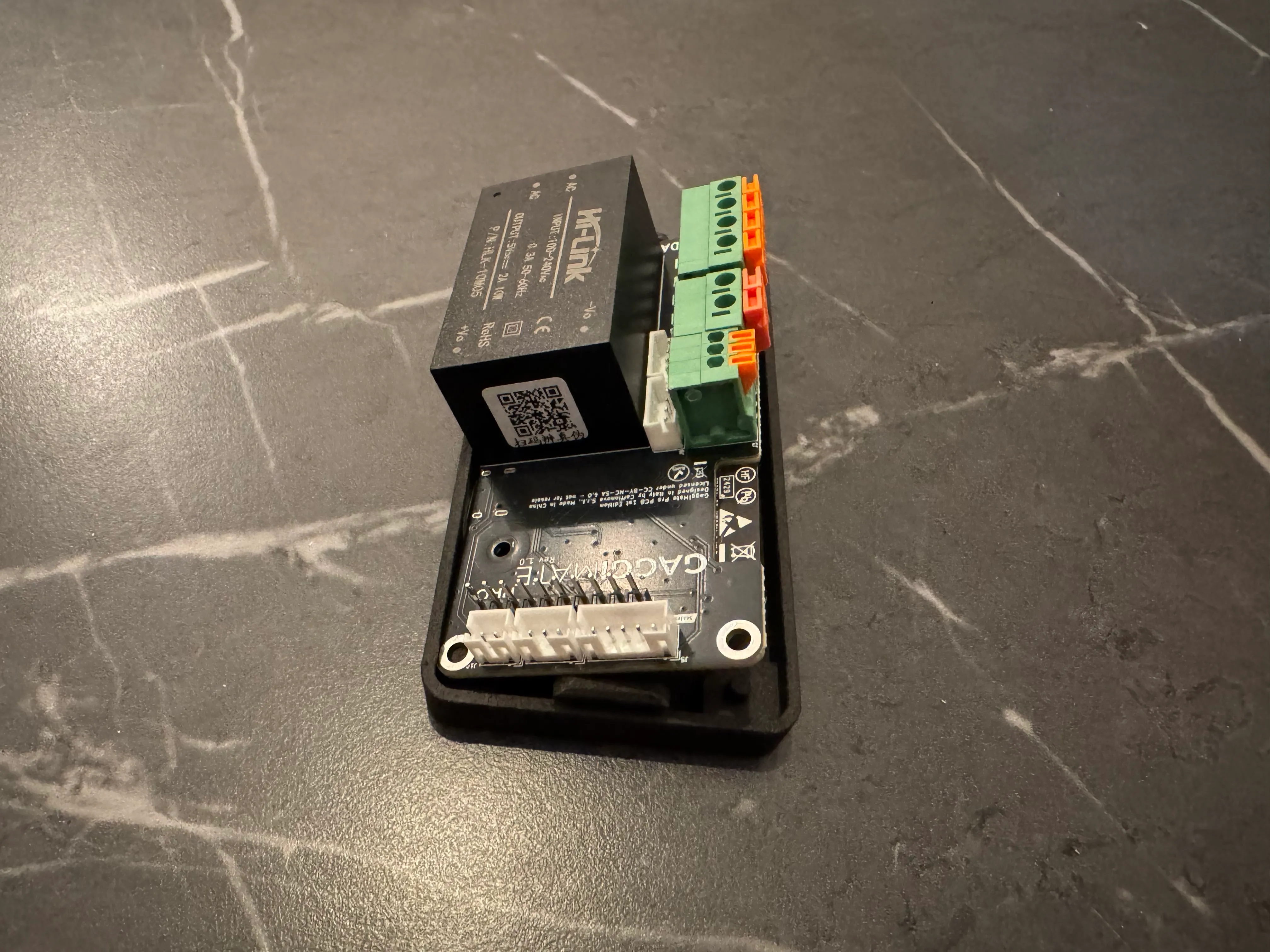
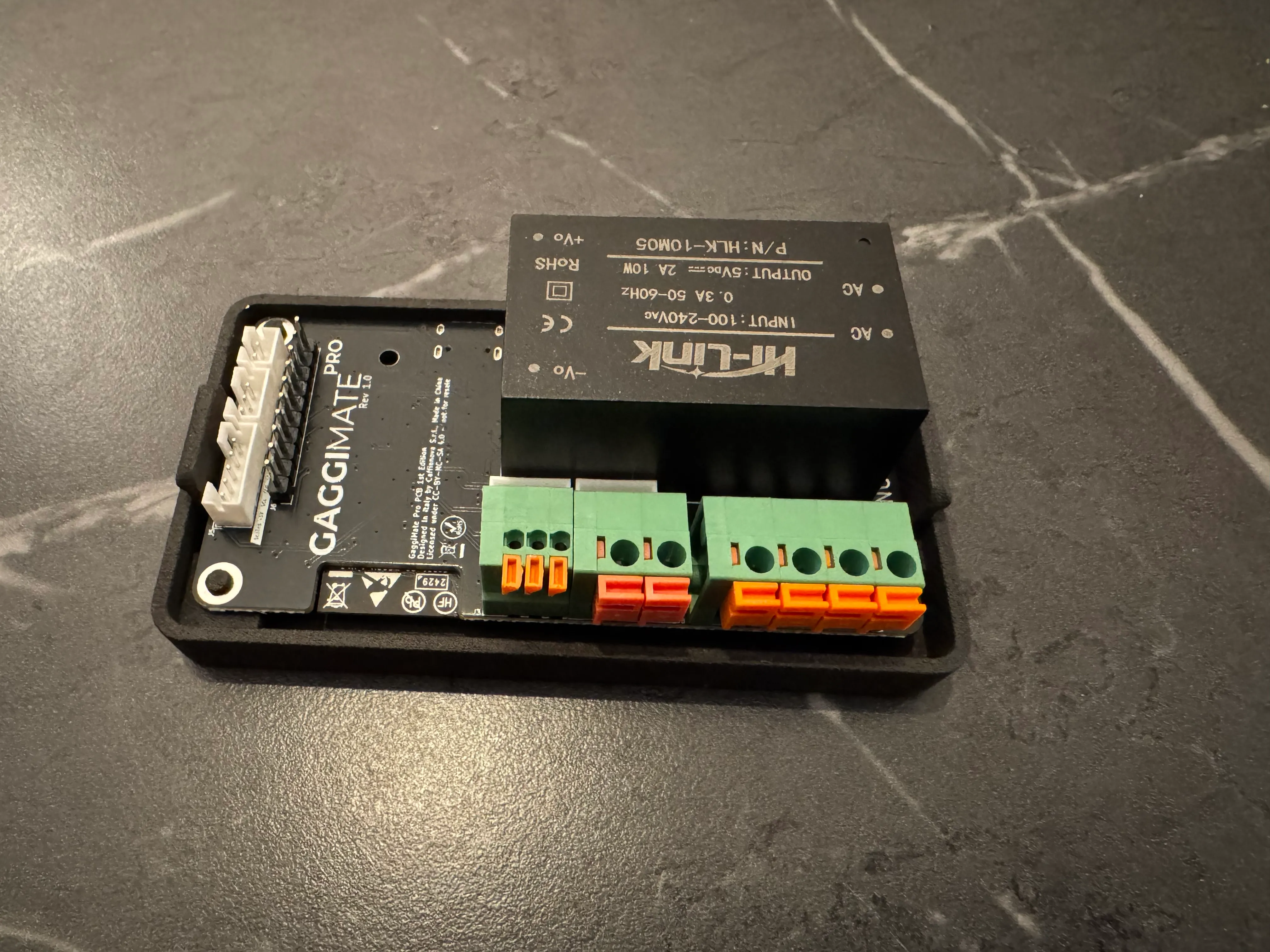
14 PCB wiring.
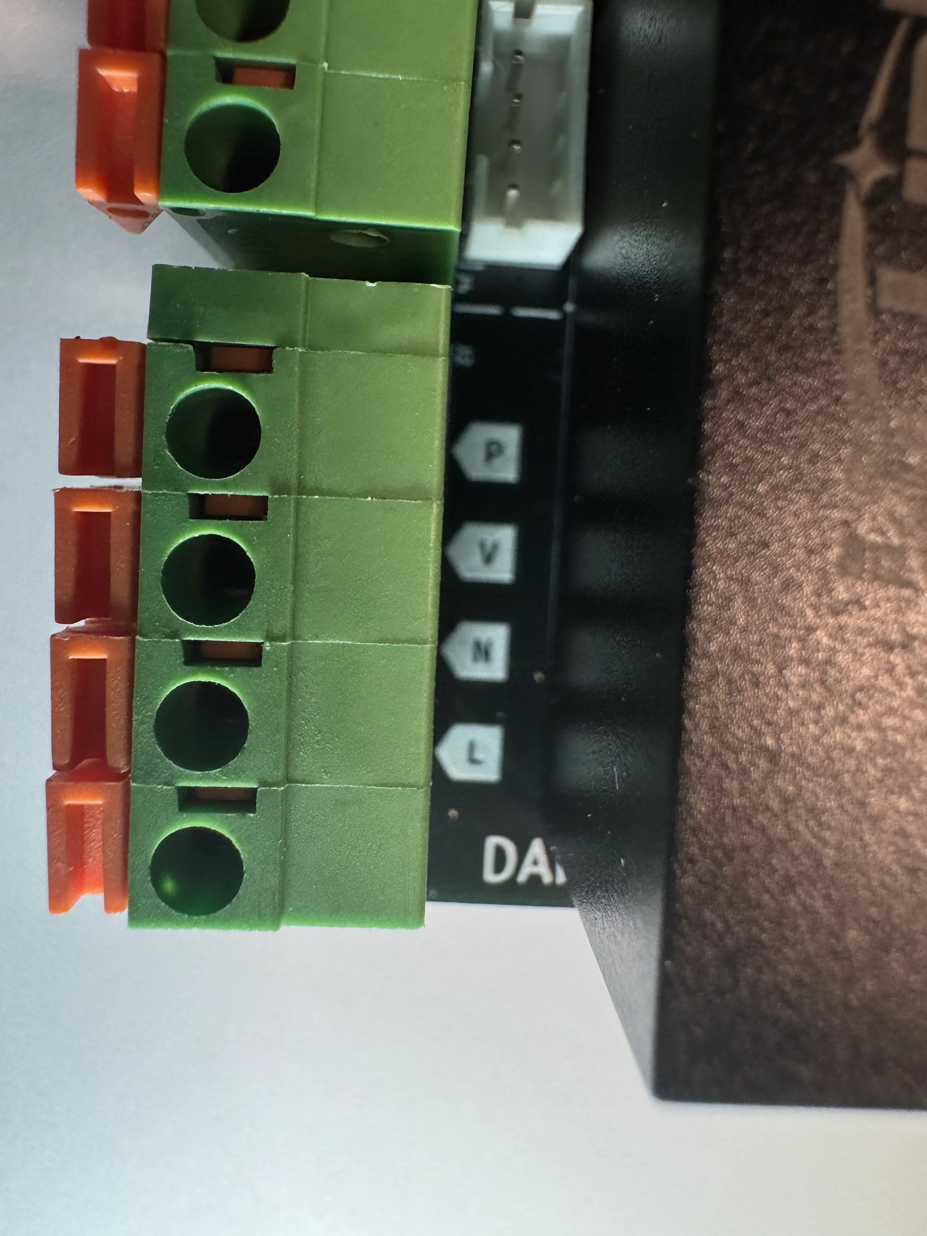
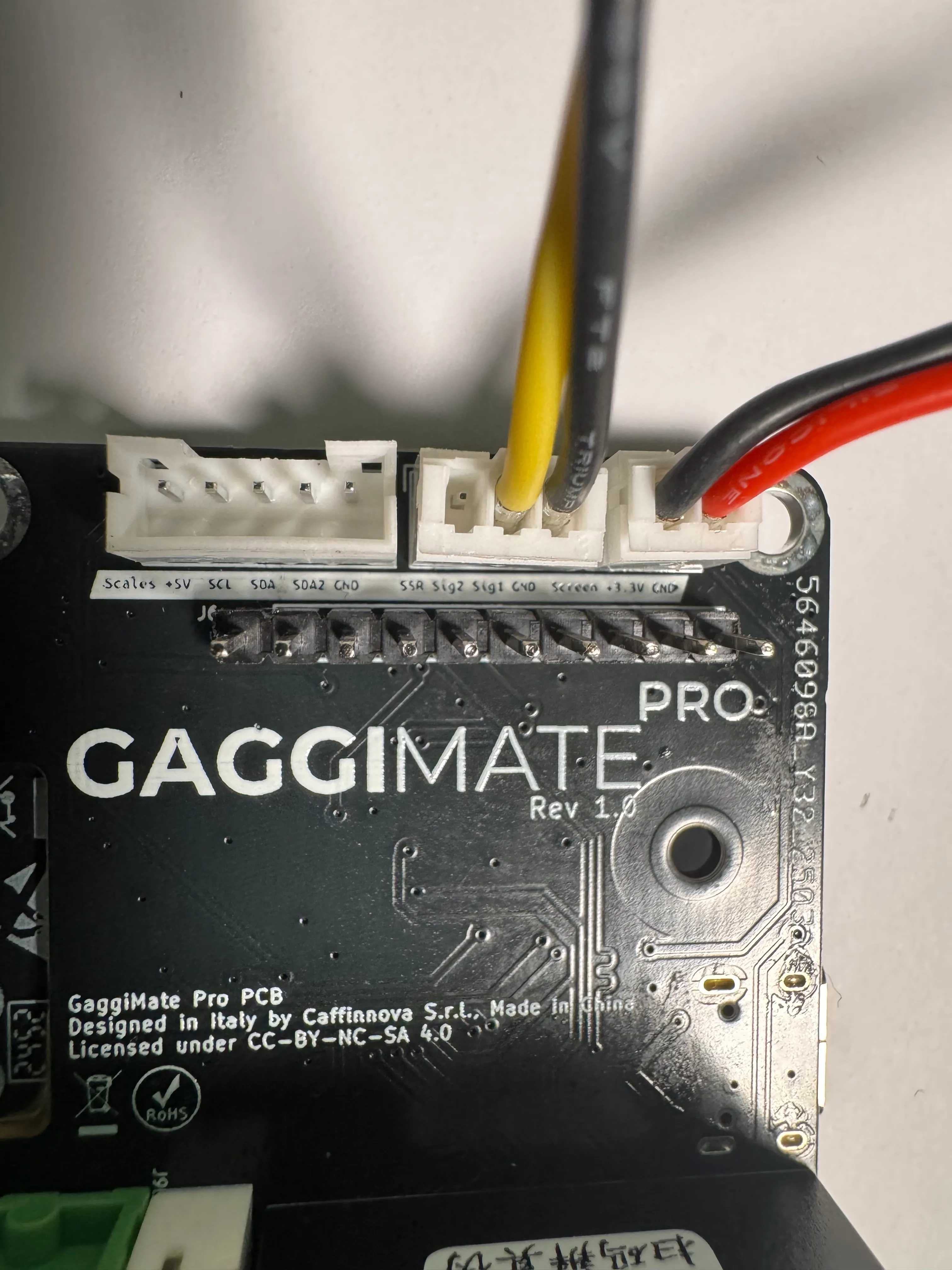
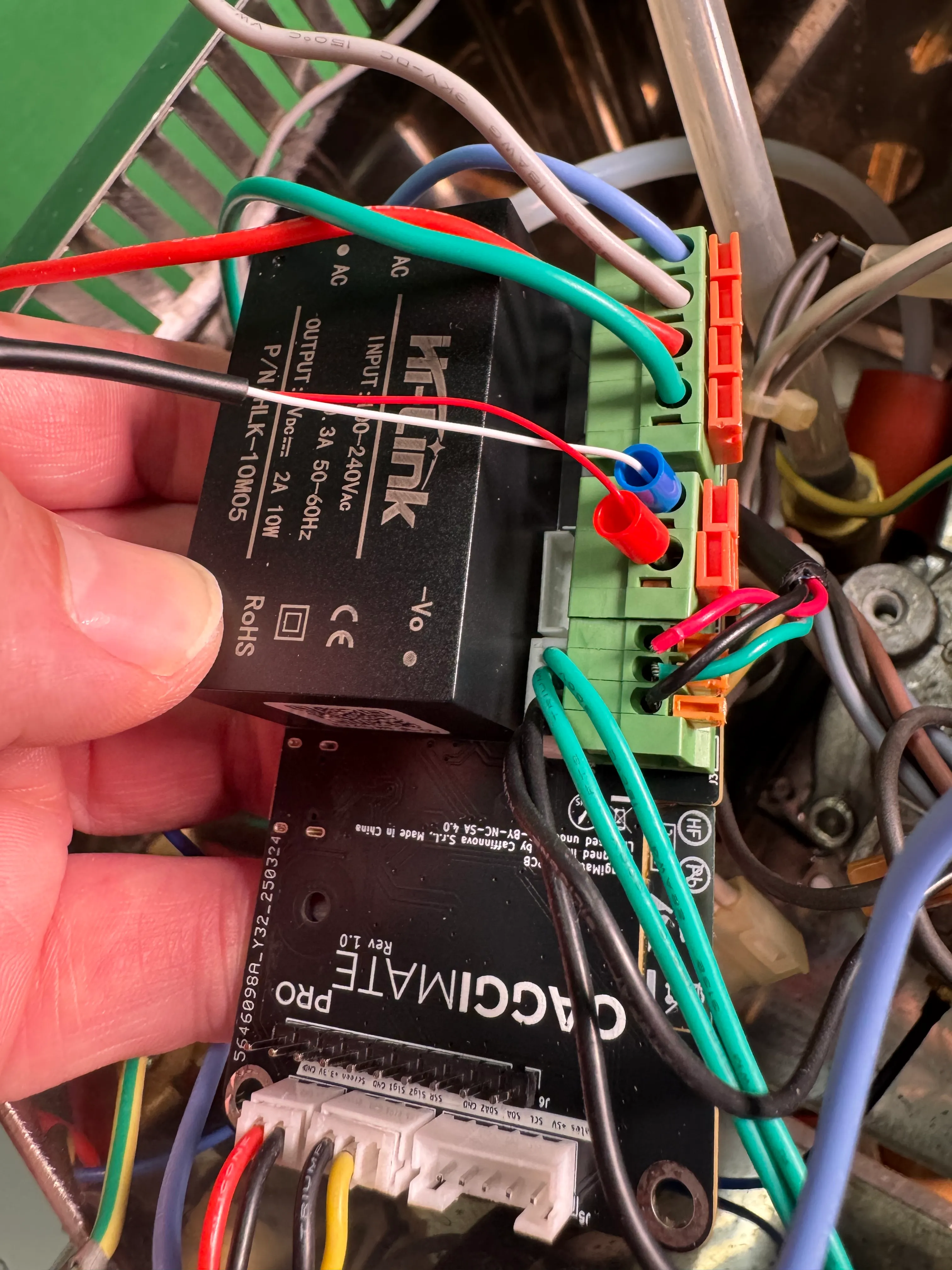
Plug in the ends of the cables into the PCB sockets. Note that they are marked on the PCB. Make sure the loose wires are fully inserted and cannot be pulled out. Your GaggiMate controller should look like the last picture above when done.
Pressure test
Before you close up the machine you’ll want to run a pressure test of the system to catch any leaks. For this you can simply run the water mode for a while and see if anything needs fixing.
Double-Check All Connections
Review all your labeled connections for accuracy and completeness. Ensure that there are no exposed wires and that all connections are secure and insulated.
Once you have completed that step, test your wiring for possible shorts with a multimeter and make sure you haven’t connected any LV connections with HV connections. Also test the switches operation for continuity in the different switch positions.
Testing
Now is the big moment. Turn on your machine for the first time. The heater should not be heating on power-on and nothing else should be running. You can check if the heater is doing anything by observing the LED on the SSR. The screen should turn on and show the Standby screen of GaggiMate. Touch the screen once to switch to warmup mode. You should see the current room temperature being displayed and the LED on the SSR will light up, indicating it’s heating up. Check that nothing is leaking inside the machine.
Final Steps
Reassemble the Machine: Carefully put the panels back on, ensuring that there are no pinched wires.
Important: Conduct a Safety Check: Perform a final inspection to ensure everything is insulated and that there are no exposed wiring connections.
If you have any further questions or need additional clarifications, feel free to go into the Discord and make a help thread or post on our Subreddit.
Congratulations
You have now finished setting up your Gaggia Classic with GaggiMate and can start making coffee. To check more tasks on your first startup go to First Start. When you do the first test shots and check the system, remember that you’ll need to have a puck or blind filter in the machine to build any pressure. If you encounter any problems during the installation check our Troubleshooting guide or open a help thread in #gaggimate-help on Discord.
Have questions?
Still have questions? Join the Discord!