Installation
Rancilio Silvia
Step-by-step GaggiMate integration guide for the Rancilio Silvia espresso machine. Comprehensive instructions for hardware installation, wiring, and thermal stability upgrades.
Important Notes
High Voltage Safety: Exercise extreme caution when working with high voltage. If you are unsure about any steps, consult a professional technician.
Follow Local Codes: Ensure that your work adheres to local electrical codes and standards.
Documentation: Keep a record of your wiring setup for future reference and troubleshooting.
Contents
- 1. Preparation
- 2. Machine preparation
- 3. Heater modifications
- 4. HV Wiring
- 5. LV Wiring
- 6. Plumbing / Pressure installation
- 7. Finishing steps
1. Preparation
Safety First! Unplug your machine to ensure there’s no live connections while working on it. Work in a dry environment to prevent electrical hazards.
Read through the entire guide first to make sure any questions will be cleared before the installation. You can always contact us for help or open a help thread on our Discord.
Start by gathering all the materials and tools listed in the sourcing pages. Follow these guides if you haven’t already: Printed Parts and Flashing (Software installation).
Check the Pinout and prepare the wires if you didn’t buy the kit.
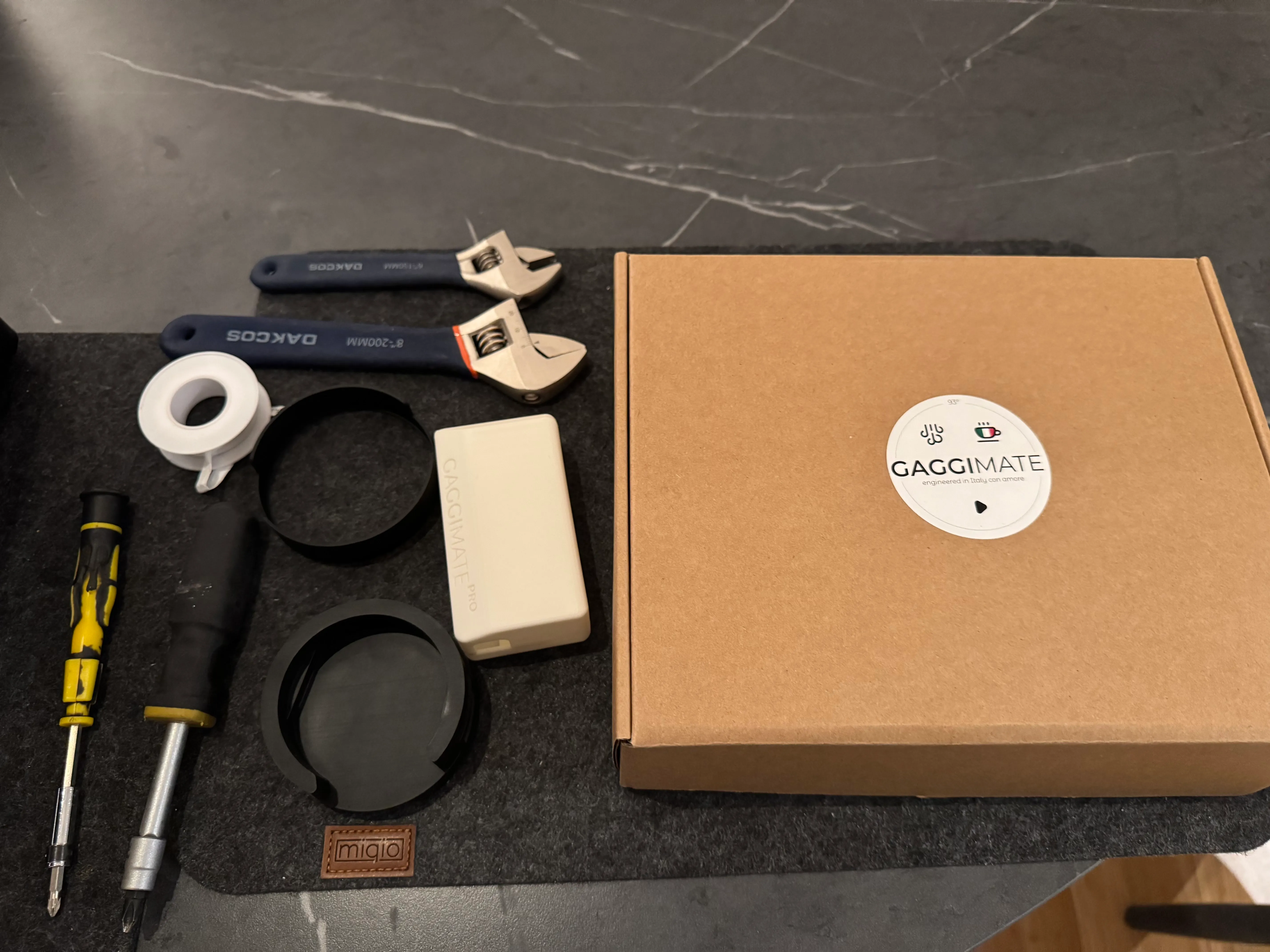
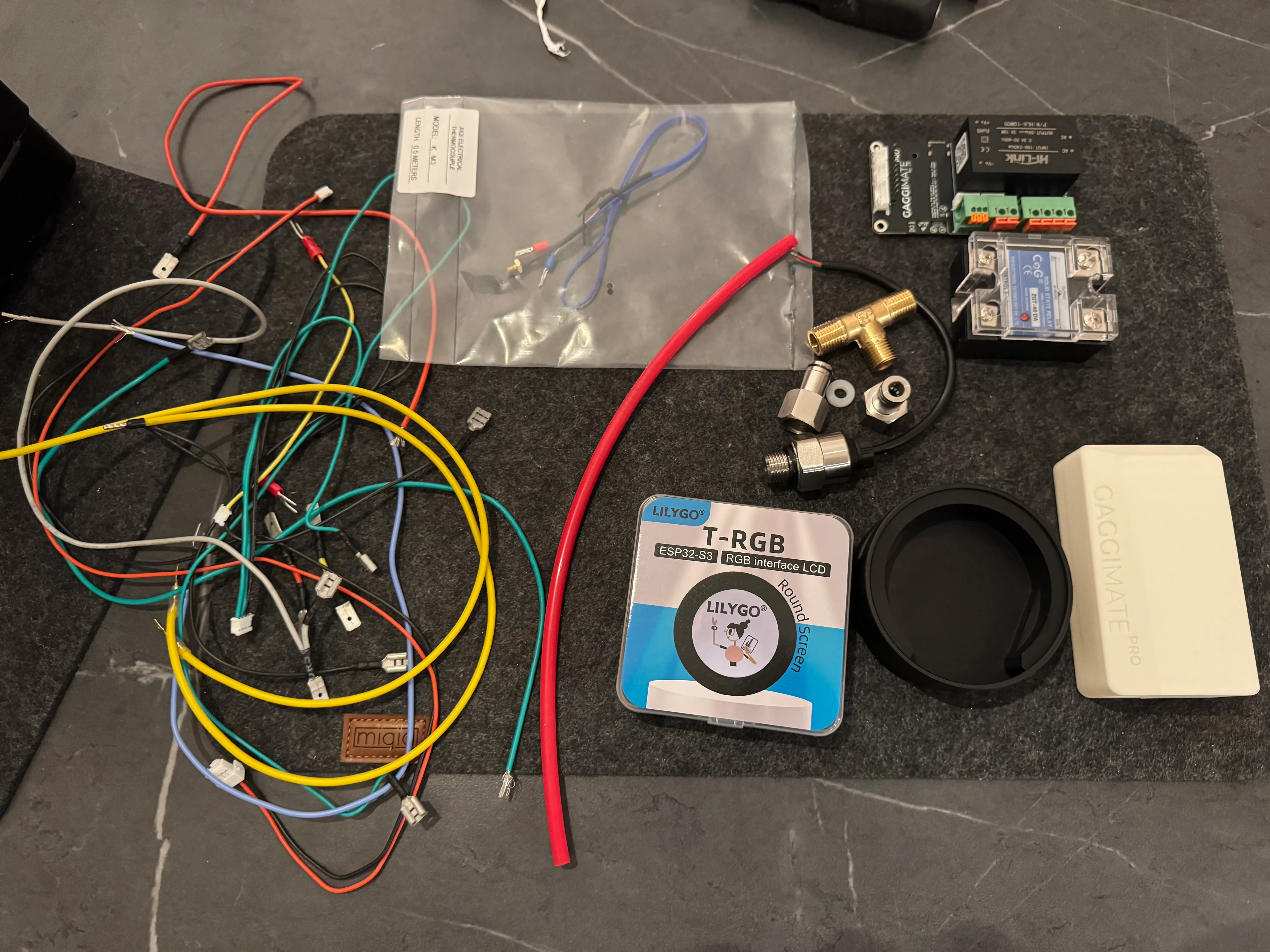
Check all the parts
Check that you have all the parts ready to go. You can see what parts and tools you might need in the pictures below.
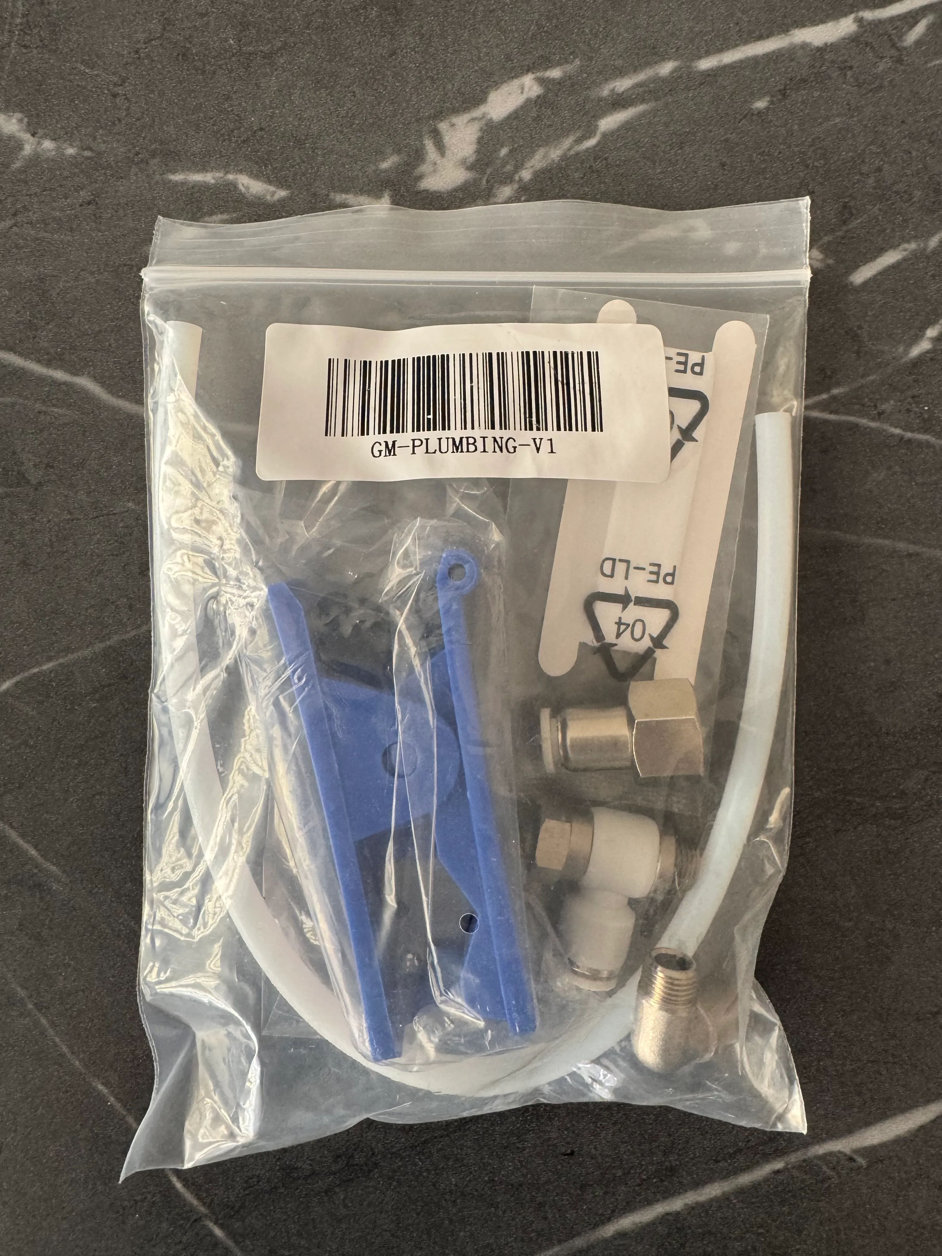
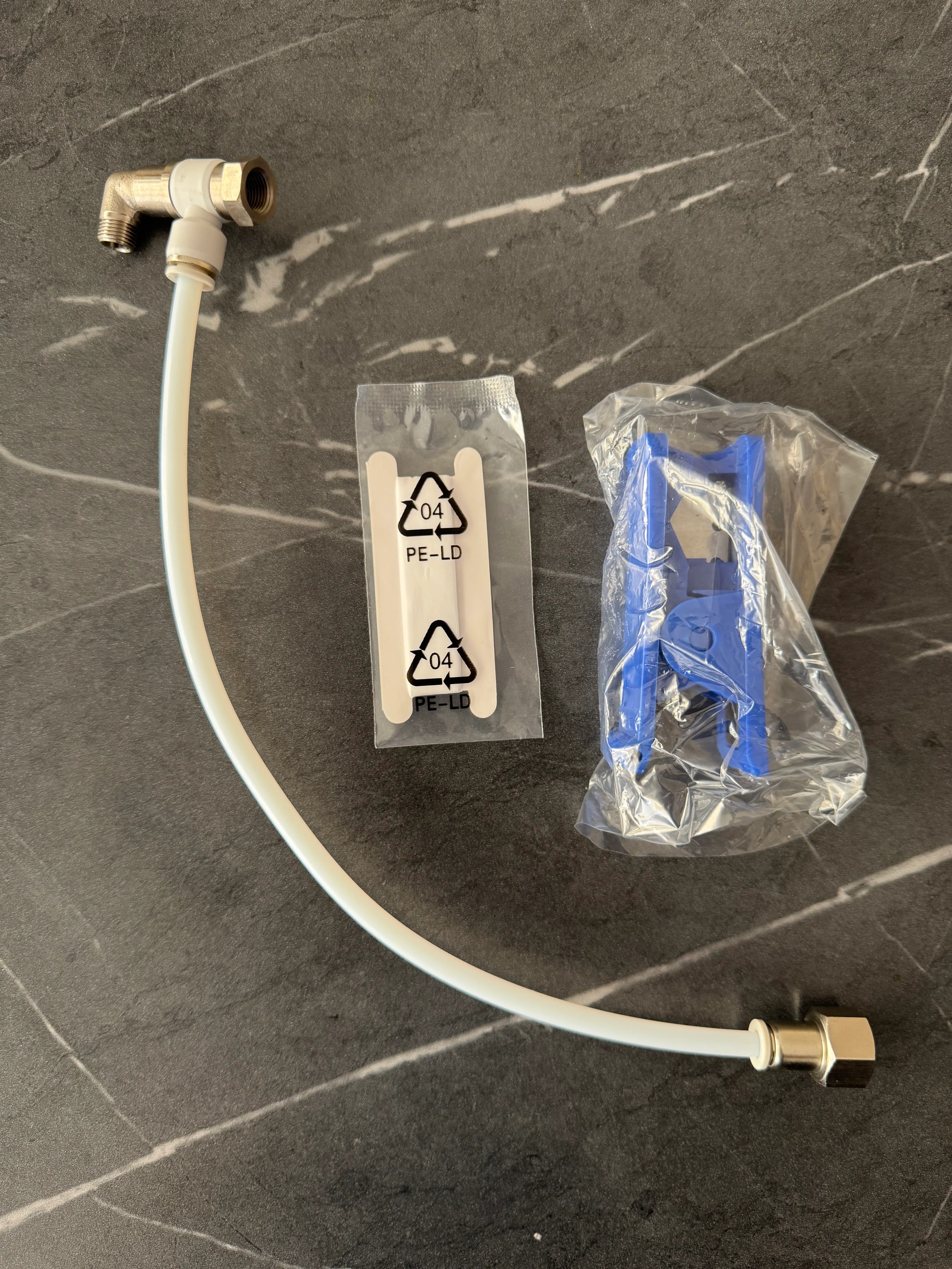
In all recent kits the plumbing parts are replaced with the parts shown on the right.
Prepare the wire labels
We’ve prepared a printable guide to label your wires in order to easier follow the install and fix mistakes. You can also just use tape, sticky labels or whatever else you have.
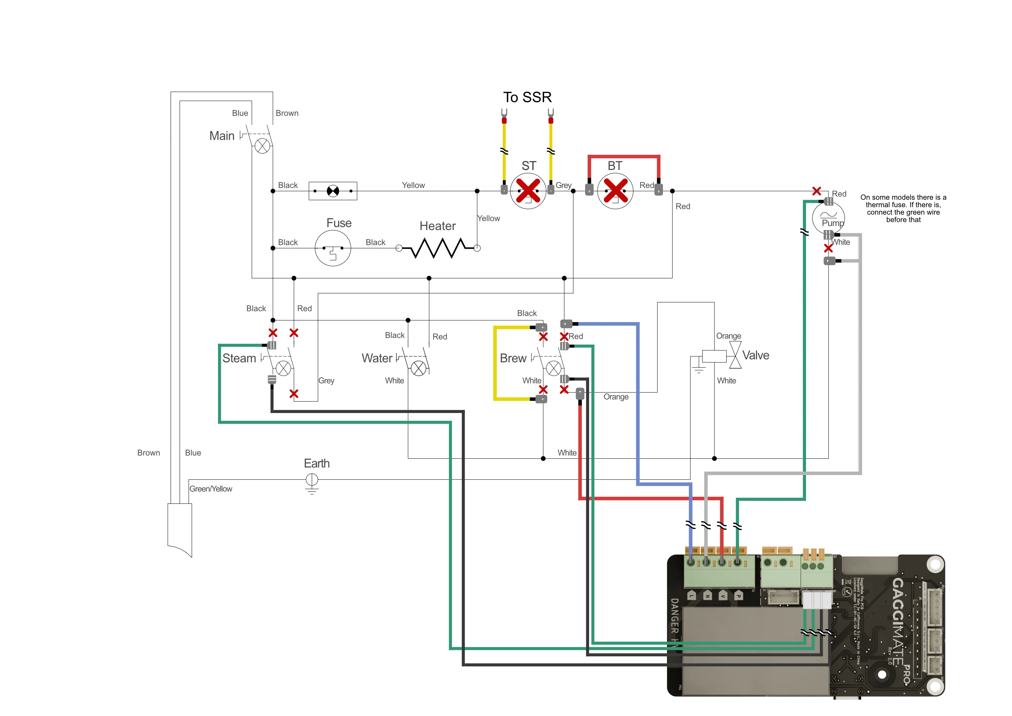
Download the wire labelsYou can check the wiring diagram for additional information.
Check the screen
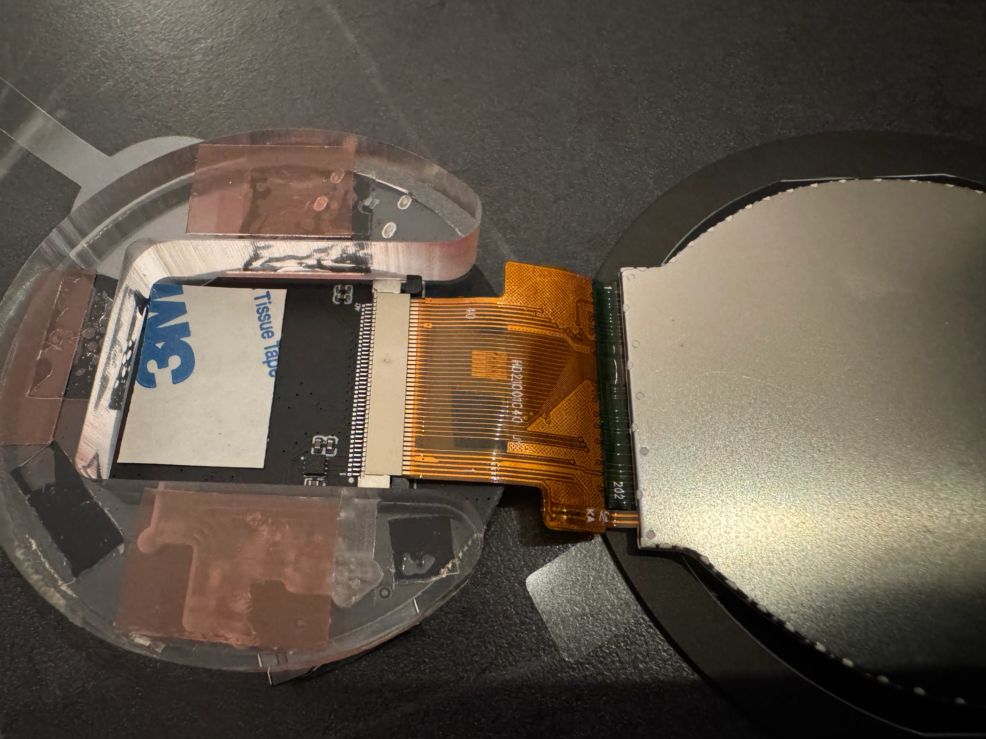
Before you assemble the screen, check that the ribbon is seated and locked correctly like in this picture. If it isn’t for any reason, unlock the connector by pulling down the black locking tab horizontally to the board, insert the cable and close it back up. Check for an image by plugging it into a USB connection before you continue.
Assemble the printed parts
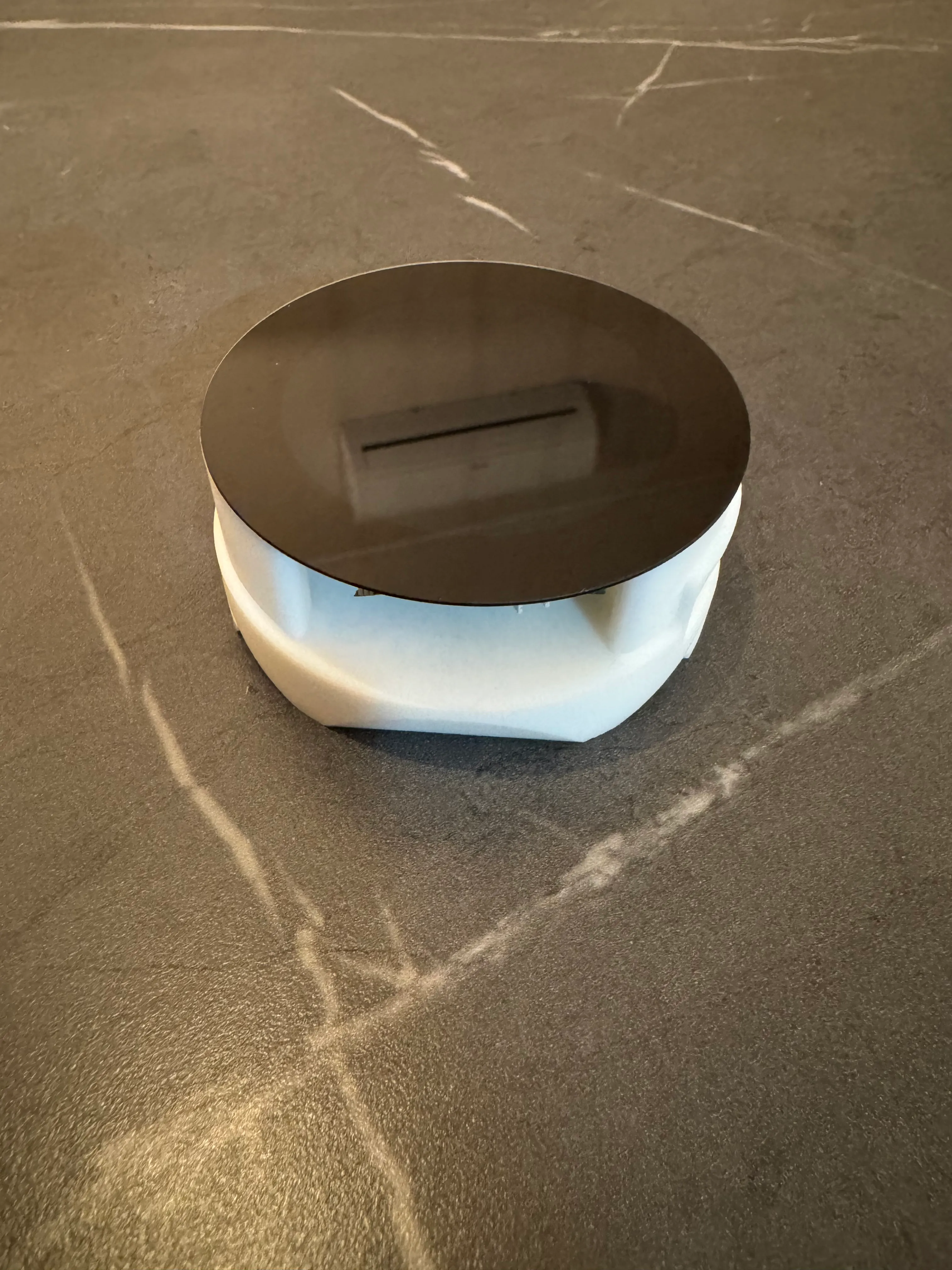
Remove the backing from the adhesive strips on the PCB part and try to stick the screen as straight and centered as possible. Place it in the base and close it gently with the cover. Be careful as the screen may fall apart easily if force is applied. There is no need to remove the plastic piece between in-between the screen and the board.
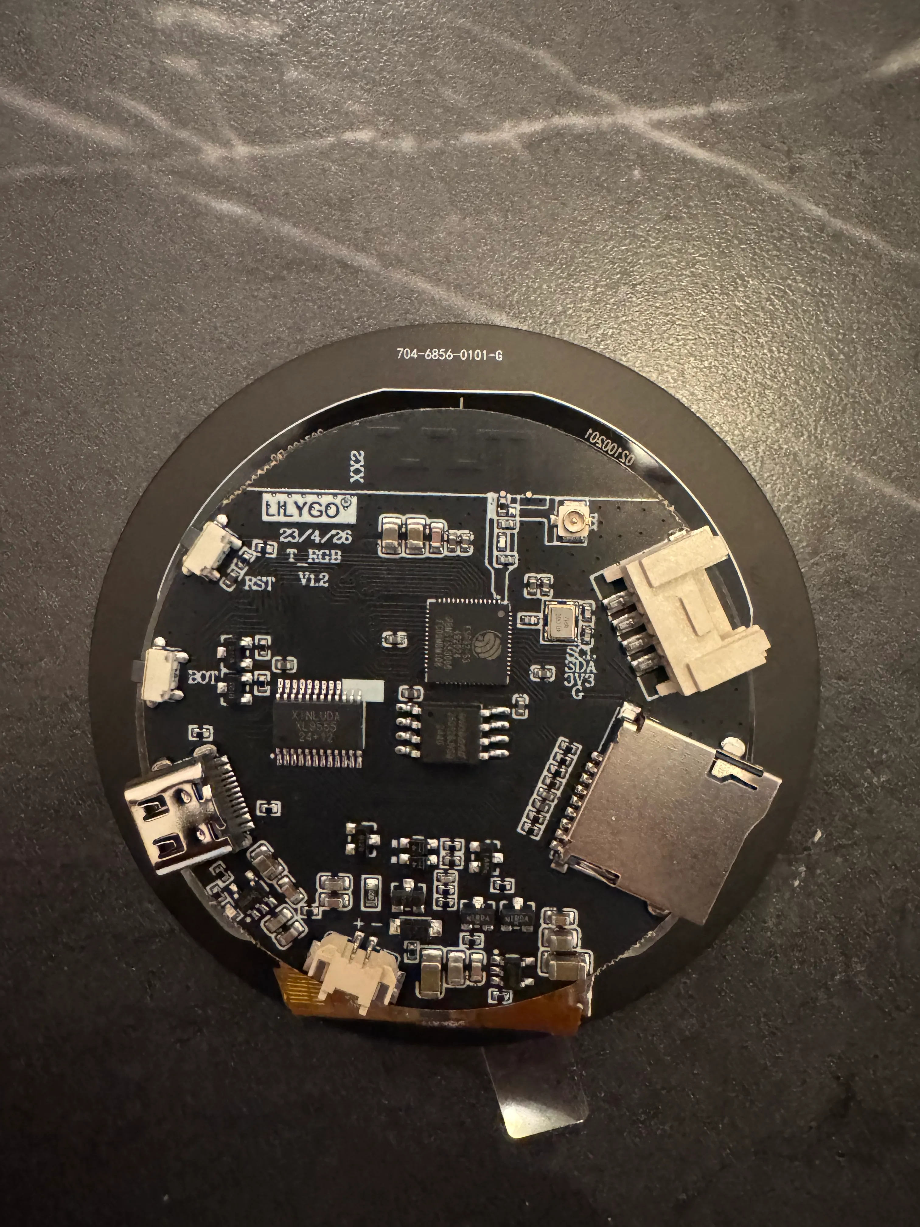
Place the PCB in the pcb cover at an angle to guide the USB-C port in the cutout. Afterwards push it down to lock it in the base. Make sure you’ve already flashed it before as you might need to access the boot button to do so.
2. Machine preparation
Disassemble the machine
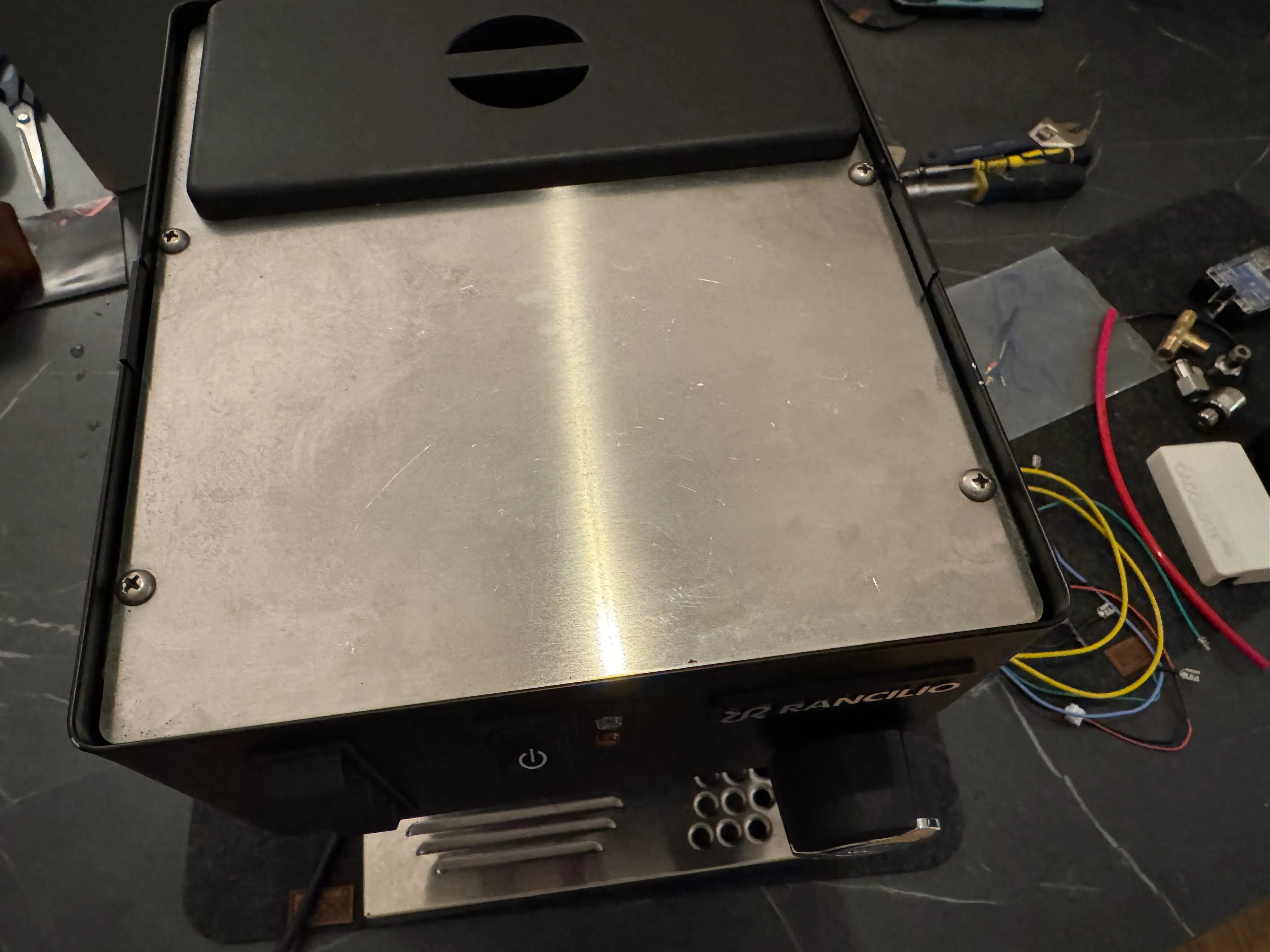
Remove all parts from the machine that could bother you during the installation or fall out like the water lid, tank, drip tray and portafilter. Undo the four screws holding the cup warmer to the case.
Afterwards, remove the cup warmer. The machine pictured is a Rancilio Silvia V6E so it might look a little different on your machine.
Now use a long thin screwdriver to undo the screw at the bottom of the case, undo the two screws around the middle holding the back part of the case on and swing the back portion upwards. Then undo the 2 screws holding on the panel that holds the tank in place. You now have access to the pump as well.
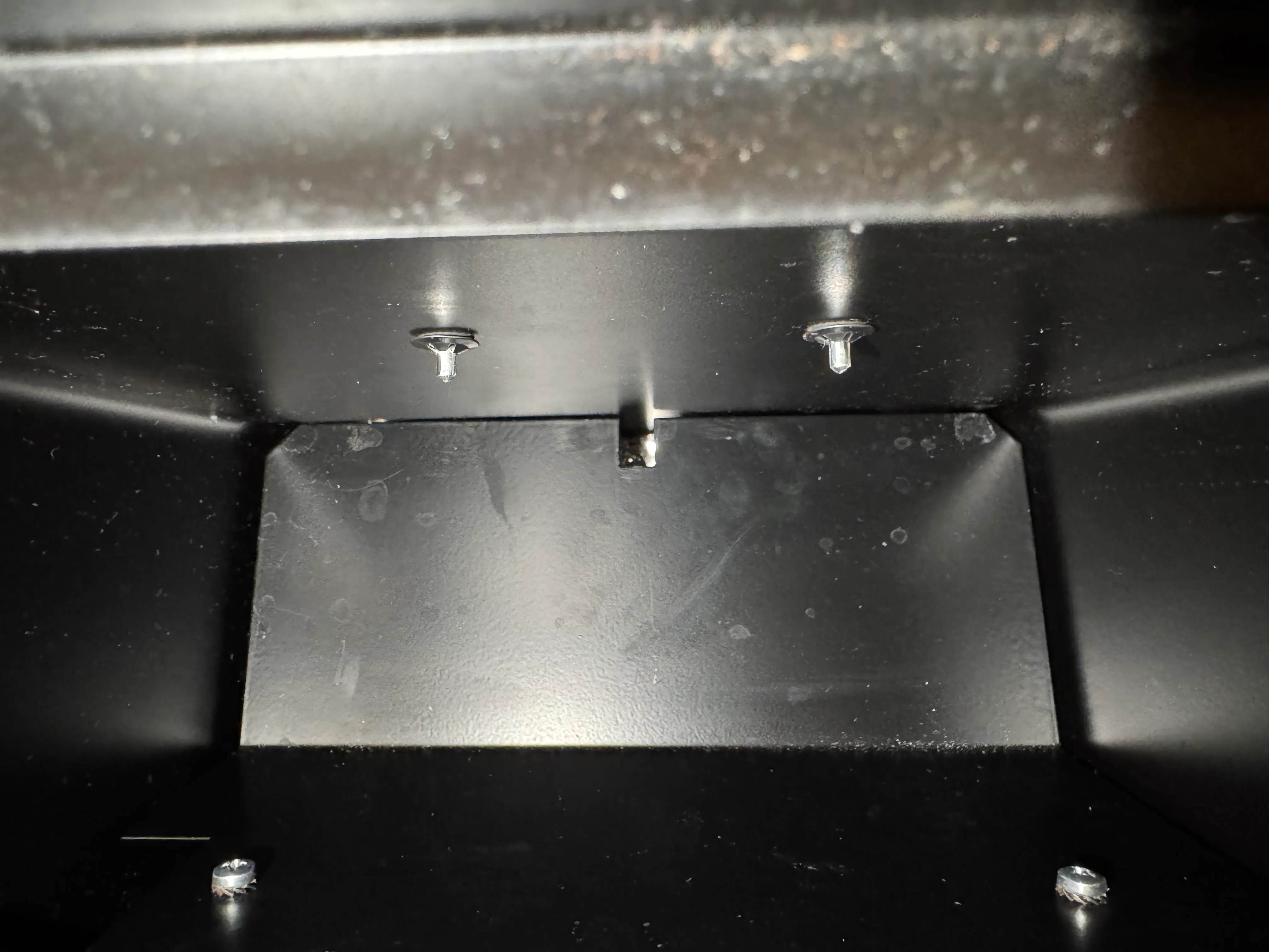
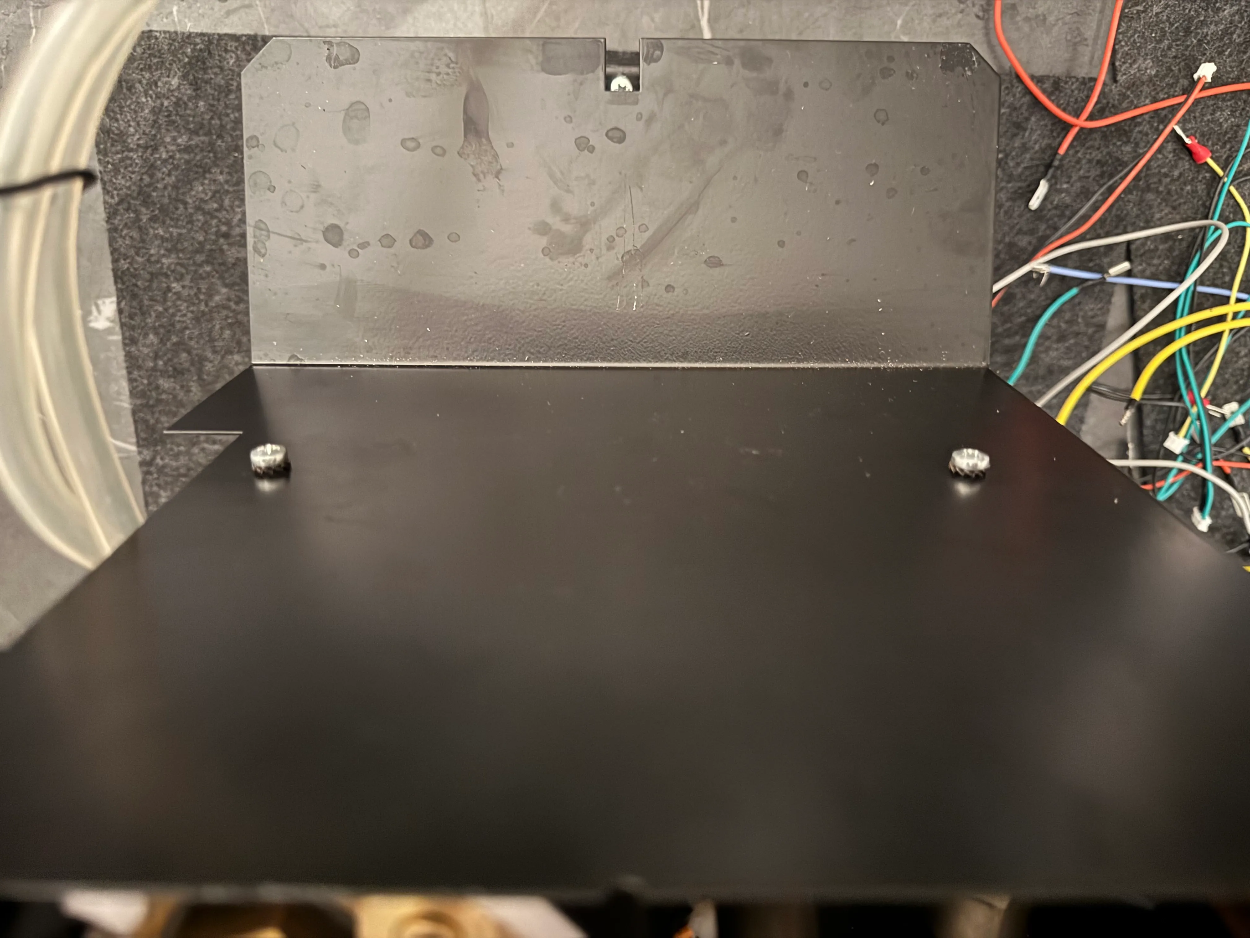
Remove the 2 screws holding on the panel underneath the grouphead and remove the panel. This is where the PCB and SSR are going to be.
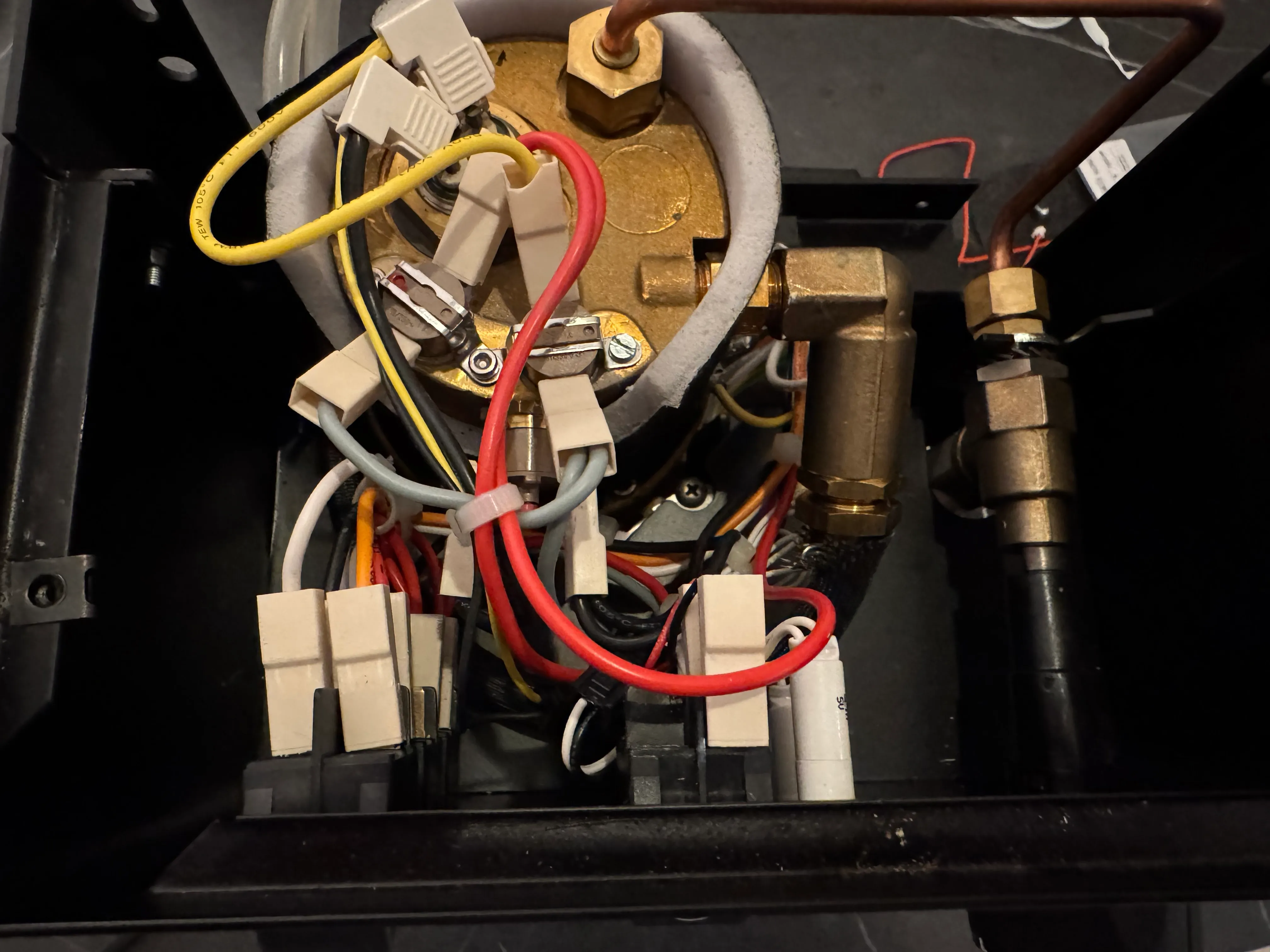
With everything removed, this is what you should be looking at.
Labeling
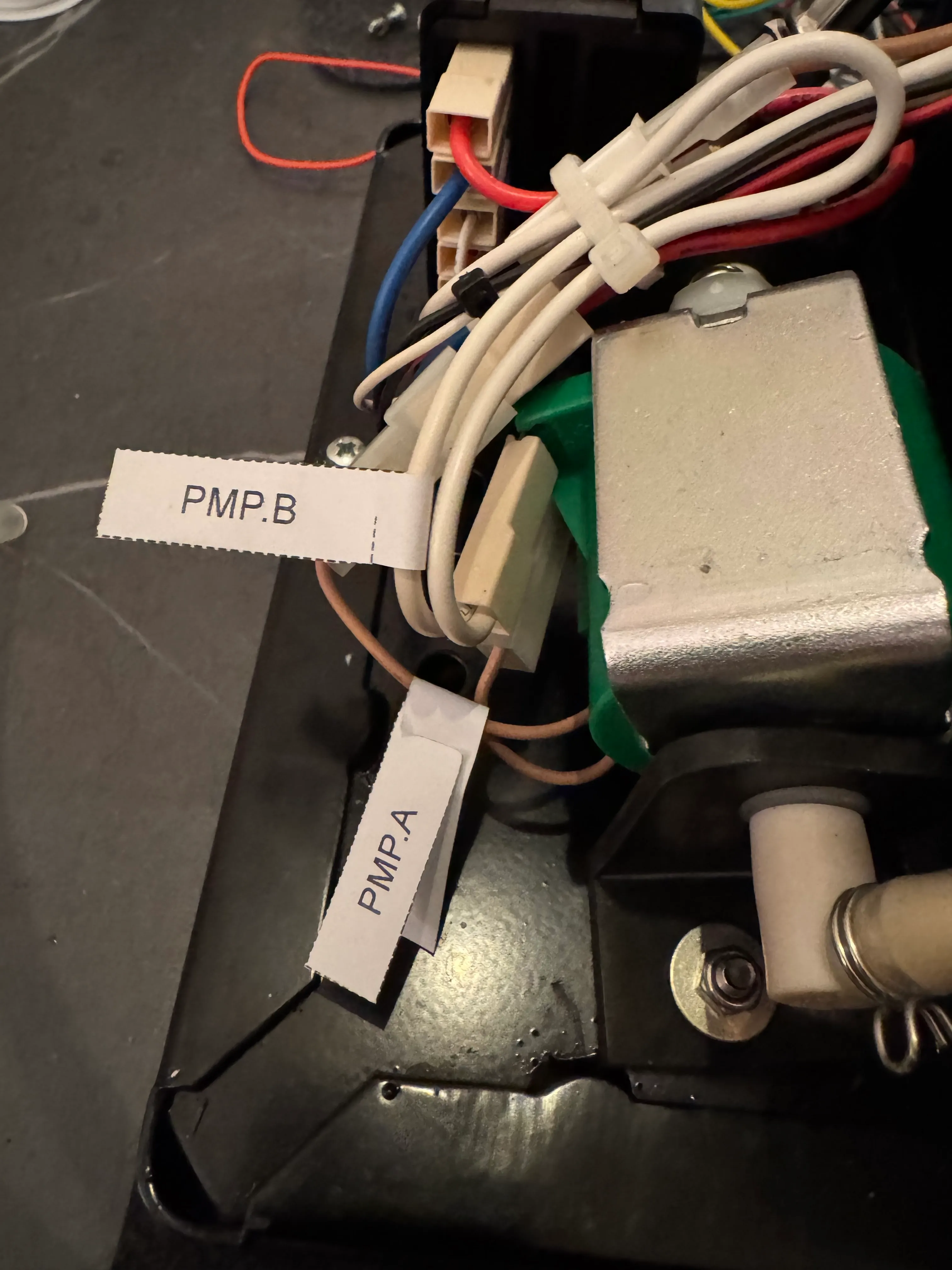
Now label all the switches and the pump with the provided labels. The order on the switches is from left to right and top to bottom when you look at them from the front of the machine. To make labeling a bit easier, you can remove the front part of the housing as well or just remove the switches.
We will refer to the numbers on the labels in the following steps.
3. Heater modifications
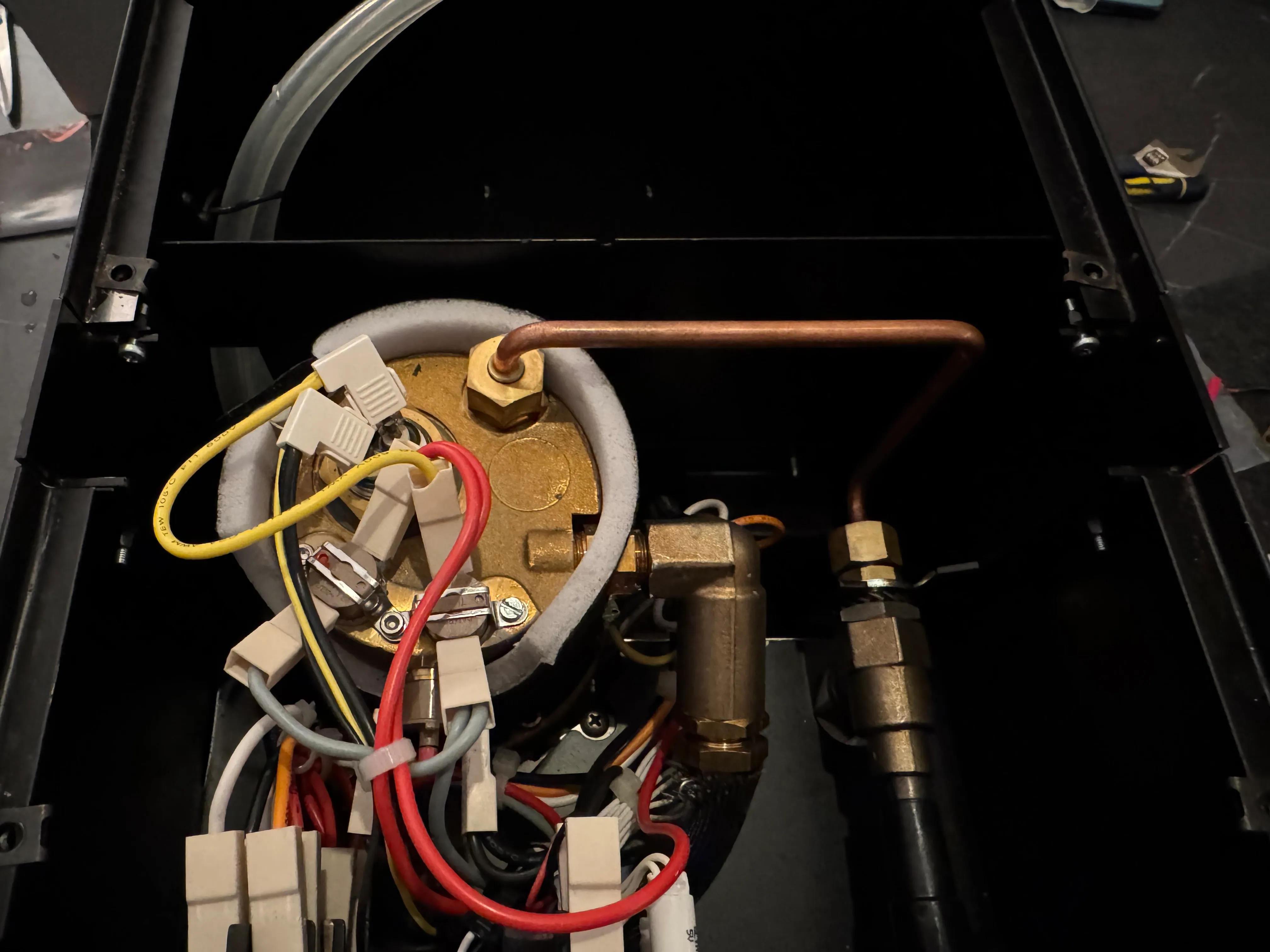
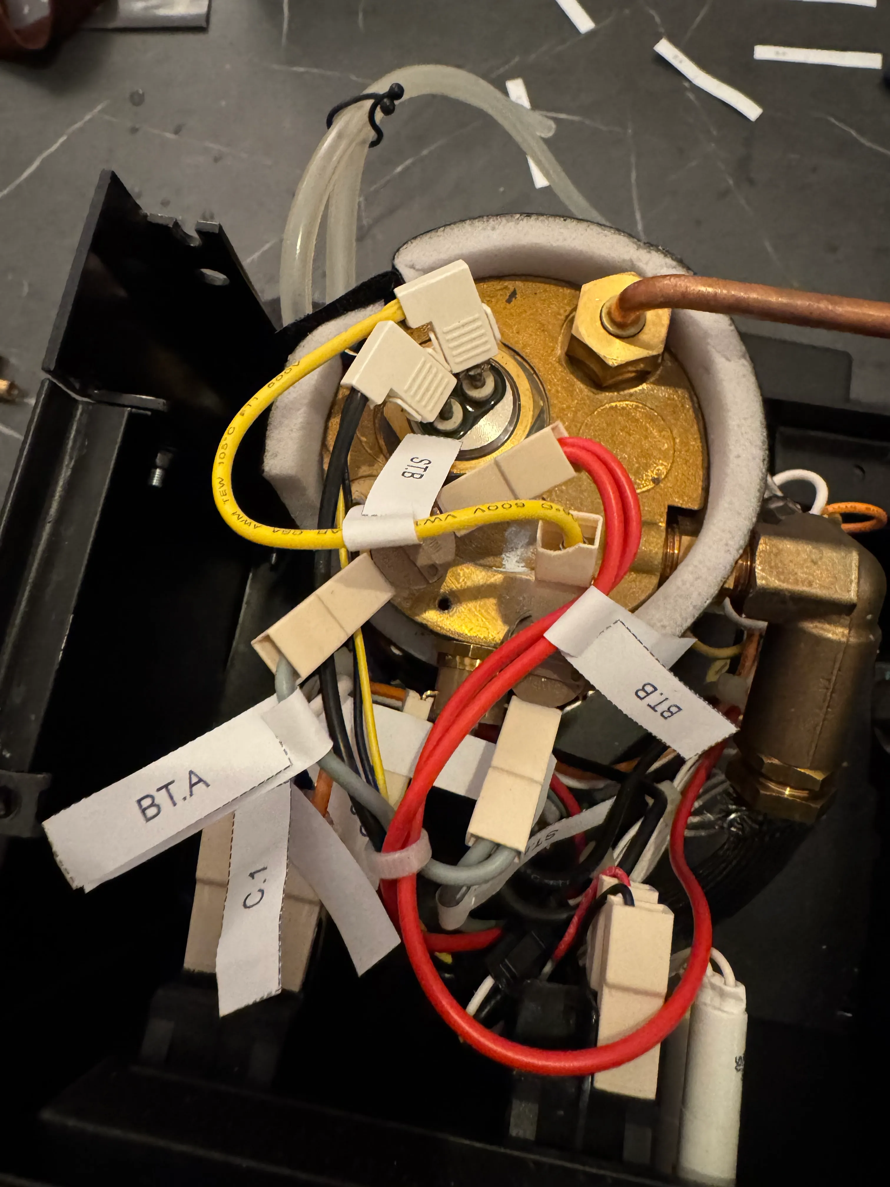
Thermostats
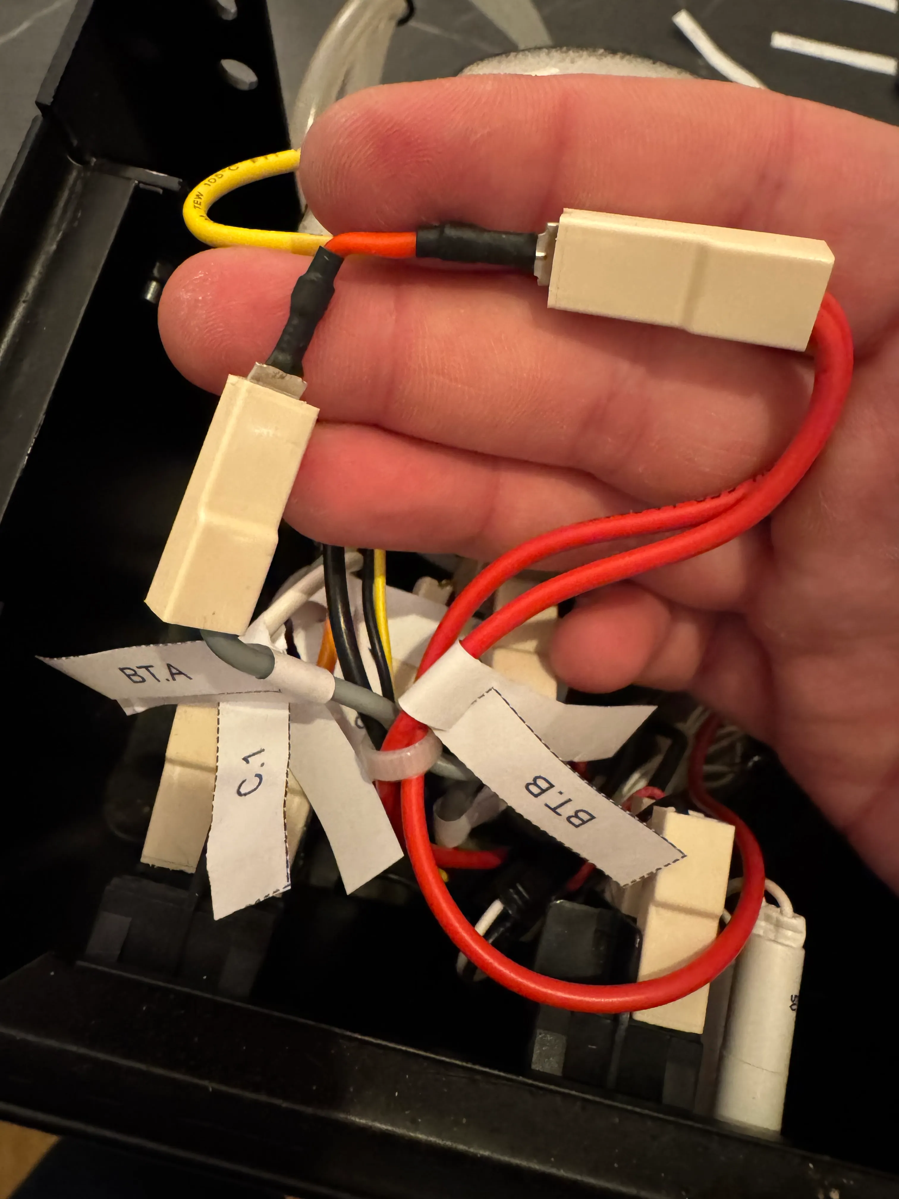
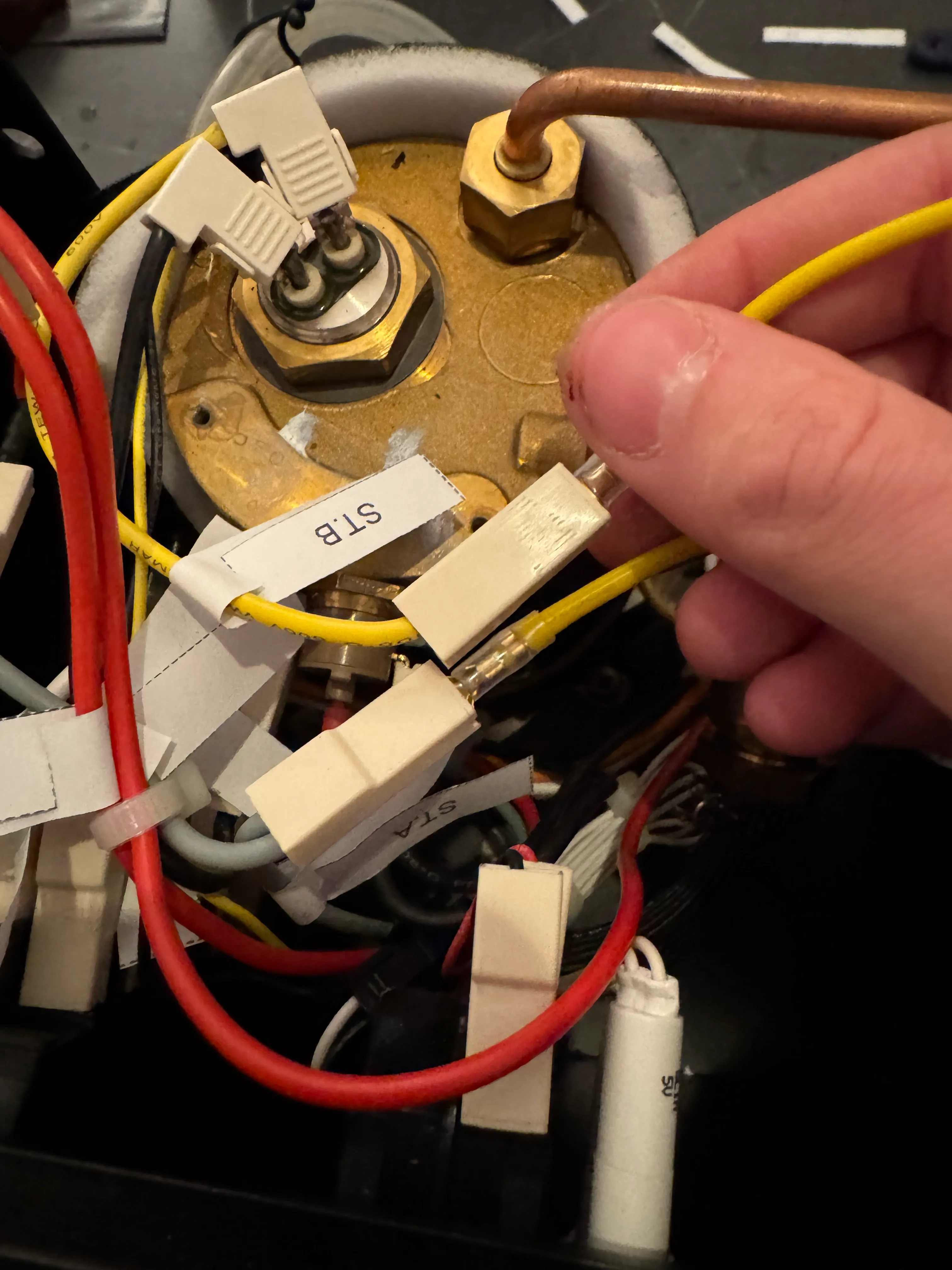
Remove both connections (BT.A, BT.B) from the brew thermostat and use the short red jumper from the wiring kit to connect those. Then remove both connections from the steam thermostat (ST.A, ST.B) and use the SSR Heater cables to extend those downwards to the front of the case.
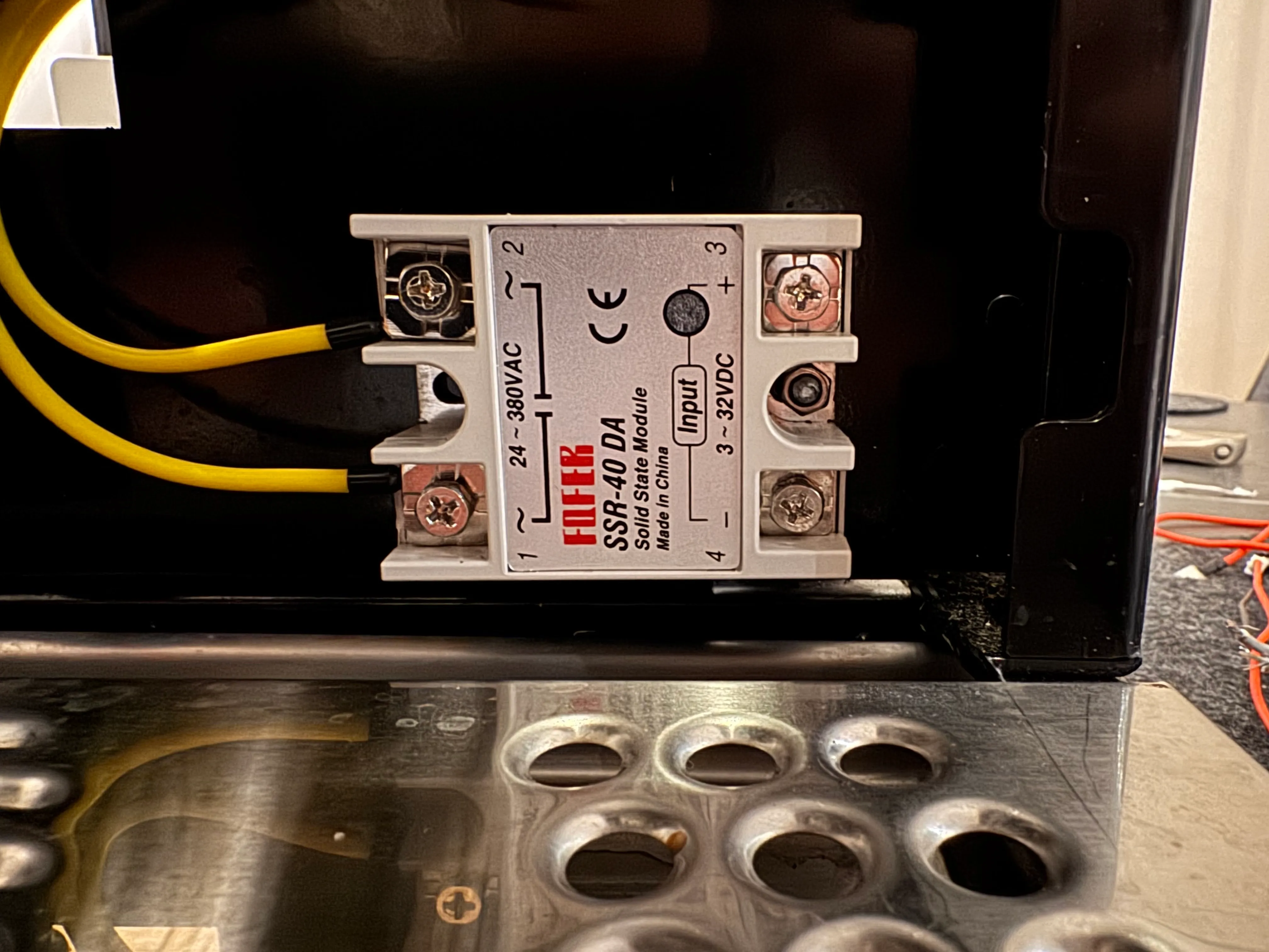
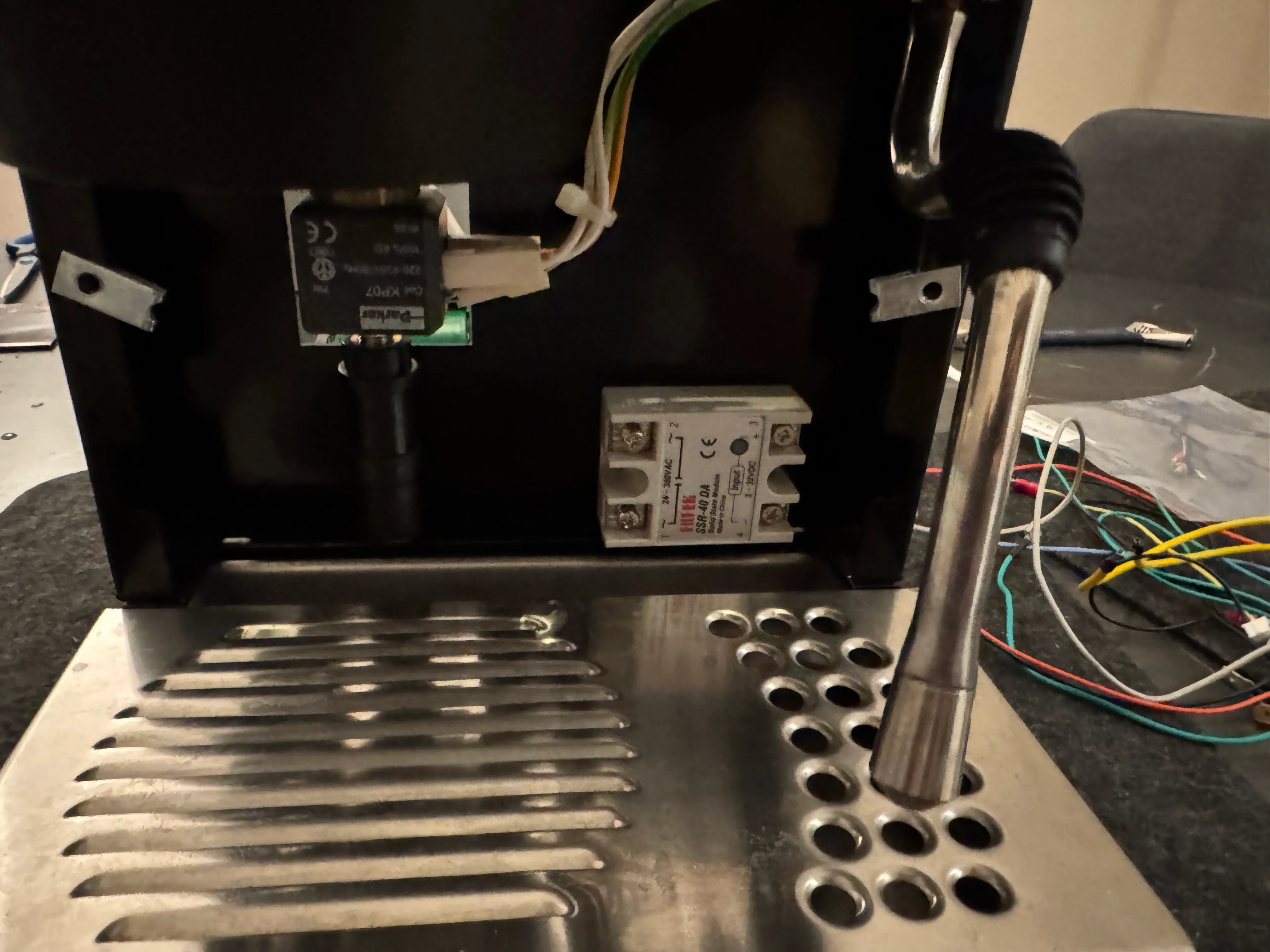
Mount the SSR on the existing screw that sticks out in the pictured area. You can access it from the back of the casing. Connect the yellow cables to the Output side of the SSR.
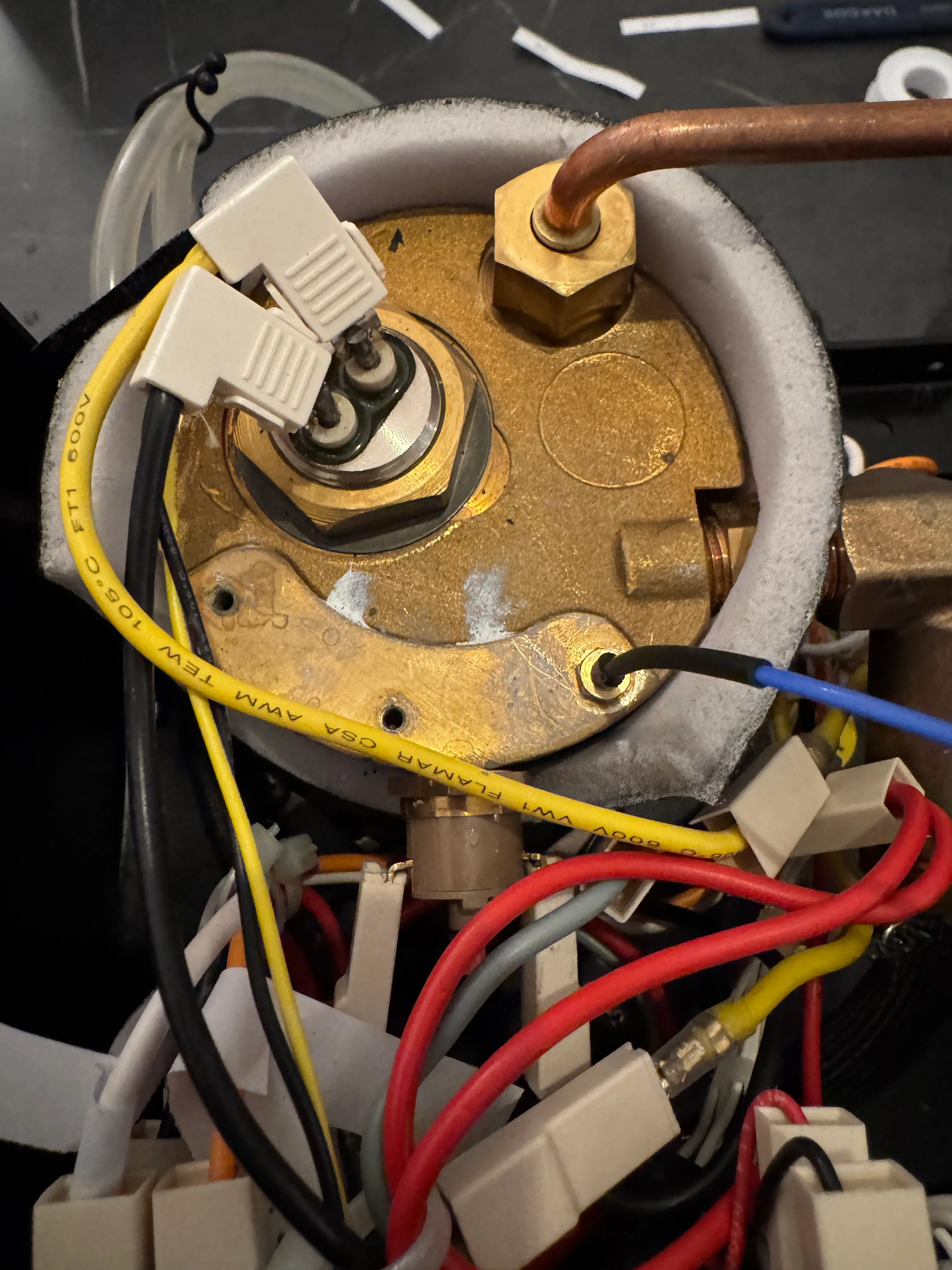
Remove the thermostats and their clamps from the boiler and screw in the M3 Thermocouple in one of the holes.
While it is shown in the right-most hole in the picture, use either the middle or left-most one for better temperature recordings.
Make sure you only screw this in hand-tight and carefully handle and rotate the wire while screwing it in. It can easily be damaged if the wire gets twisted. Route that wire to the same location the SSR is in while keeping it mostly away from the HV wires.
4. HV Wiring
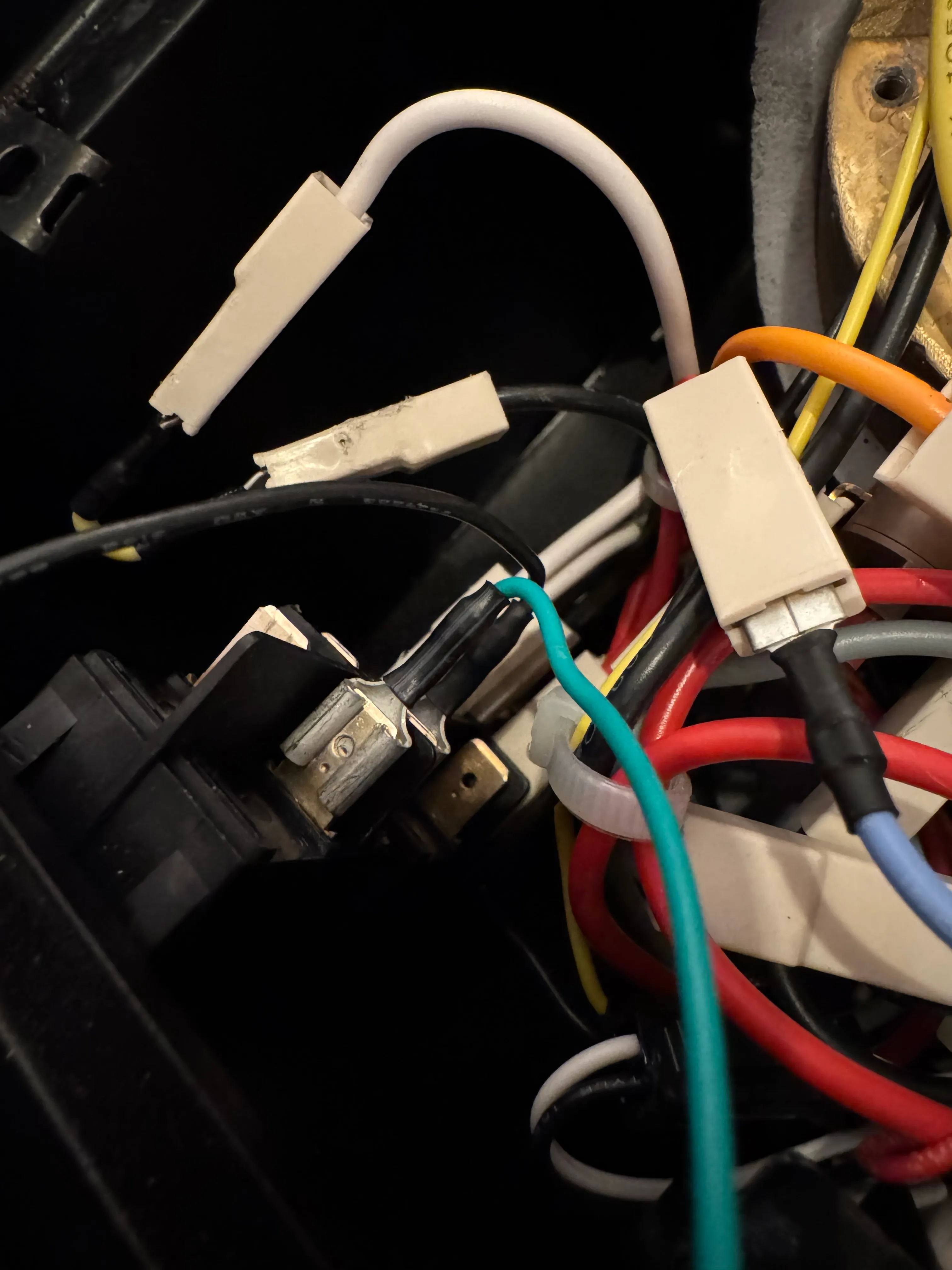
Brew switch
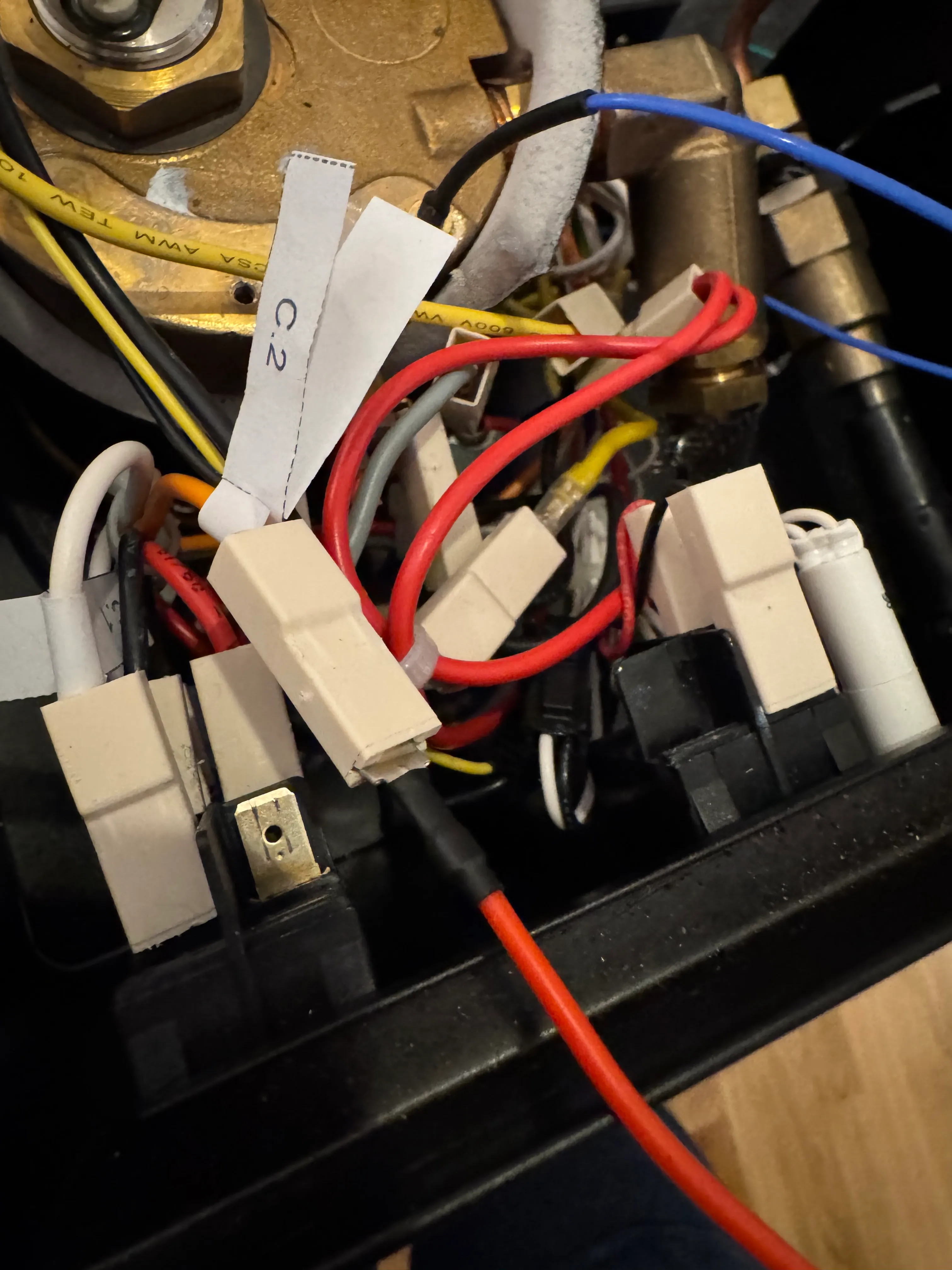
Remove the connection C.2 from the brew switch, extend it with the red cable from the wiring kit and run it to the V port of the PCB.
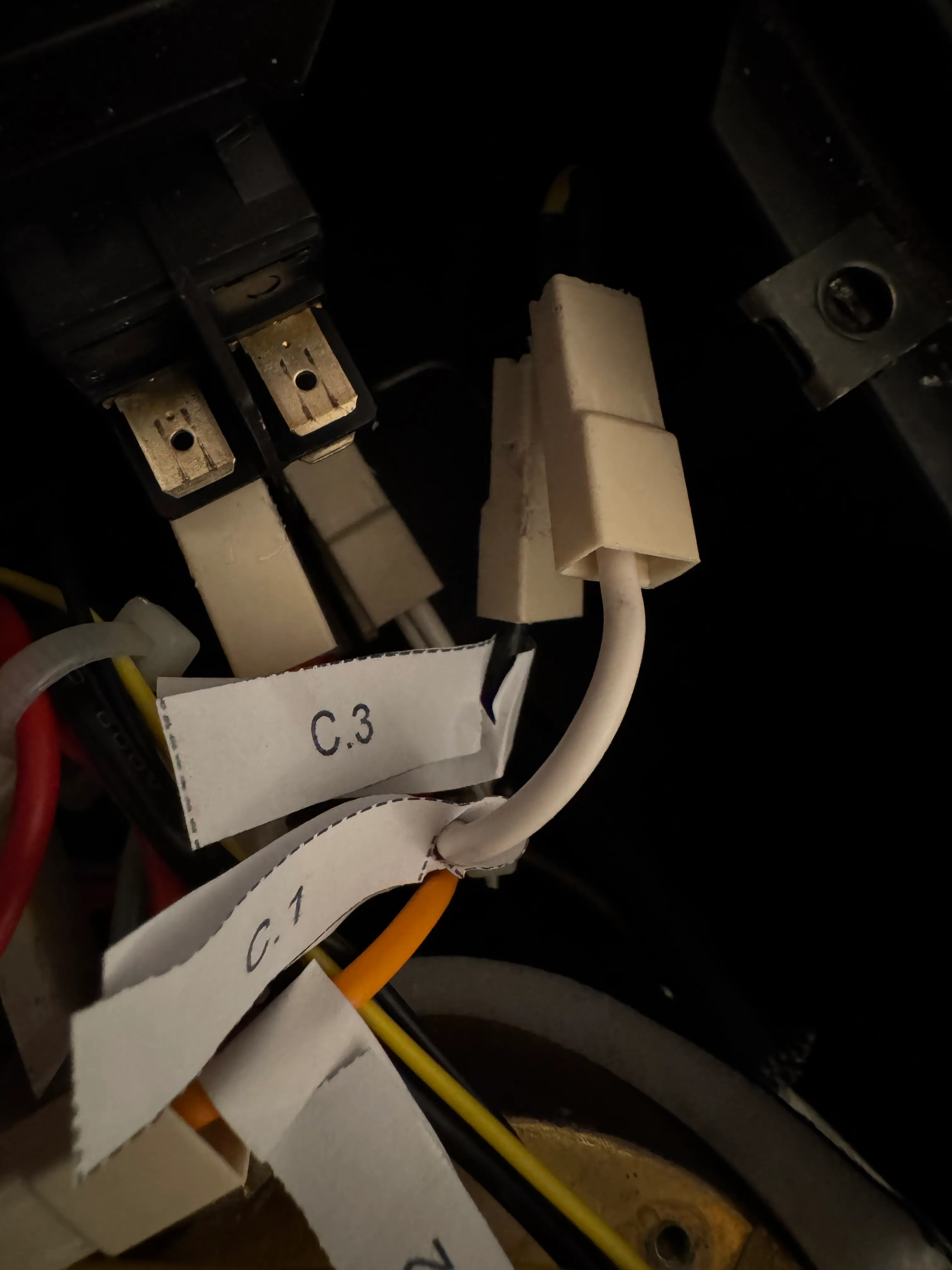
Remove the connections C.1 and C.3 from the brew switch and use the little yellow jumper from the wiring kit to bridge them.
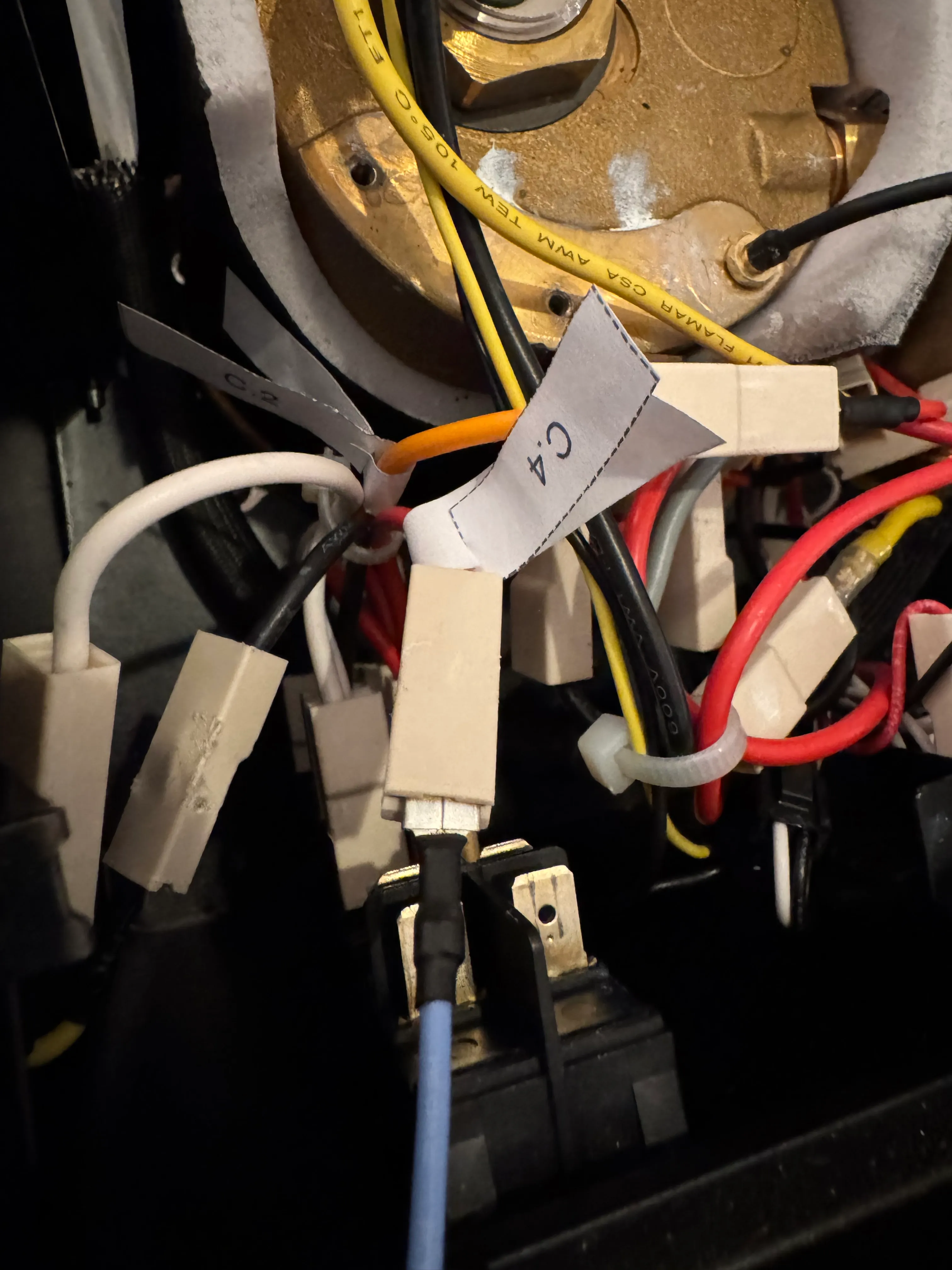
Remove the connection C.4 from the brew switch, extend it with the blue cable from the wiring kit and run it to the L port of the PCB.
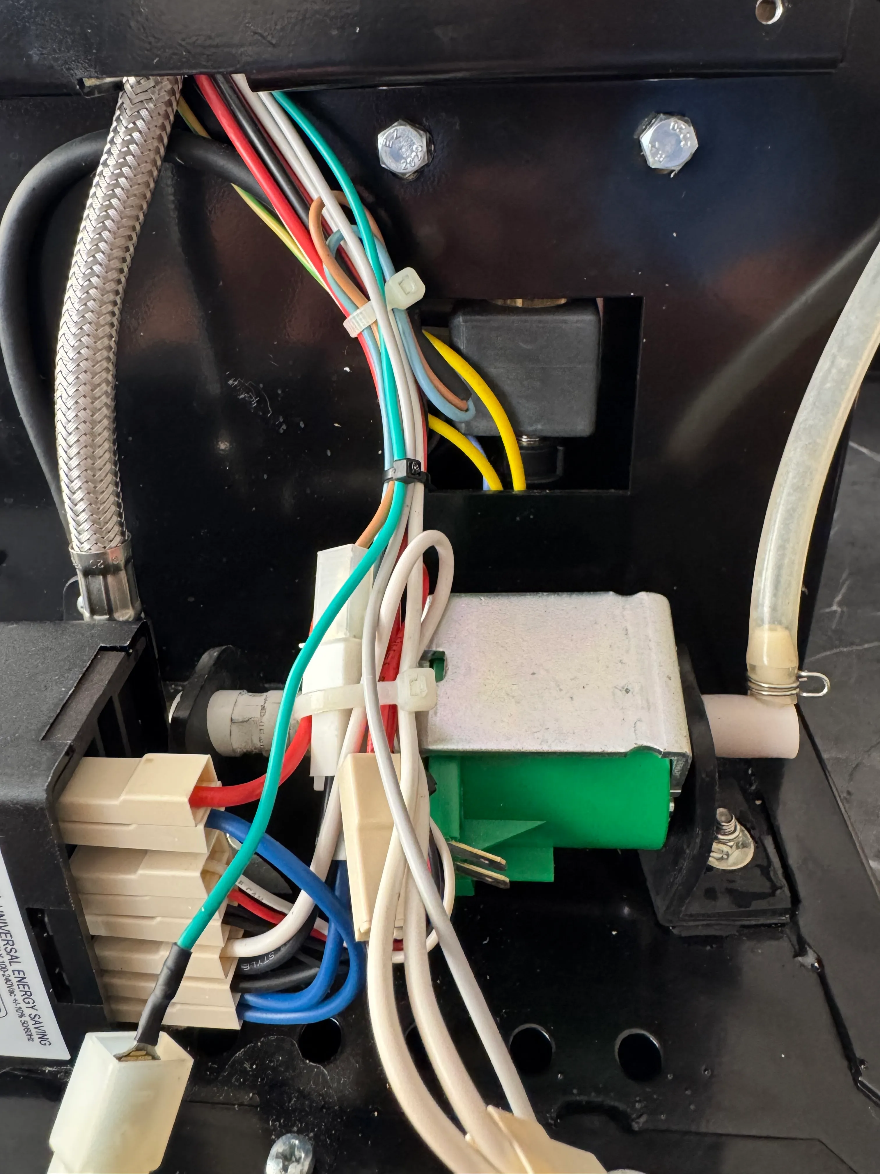
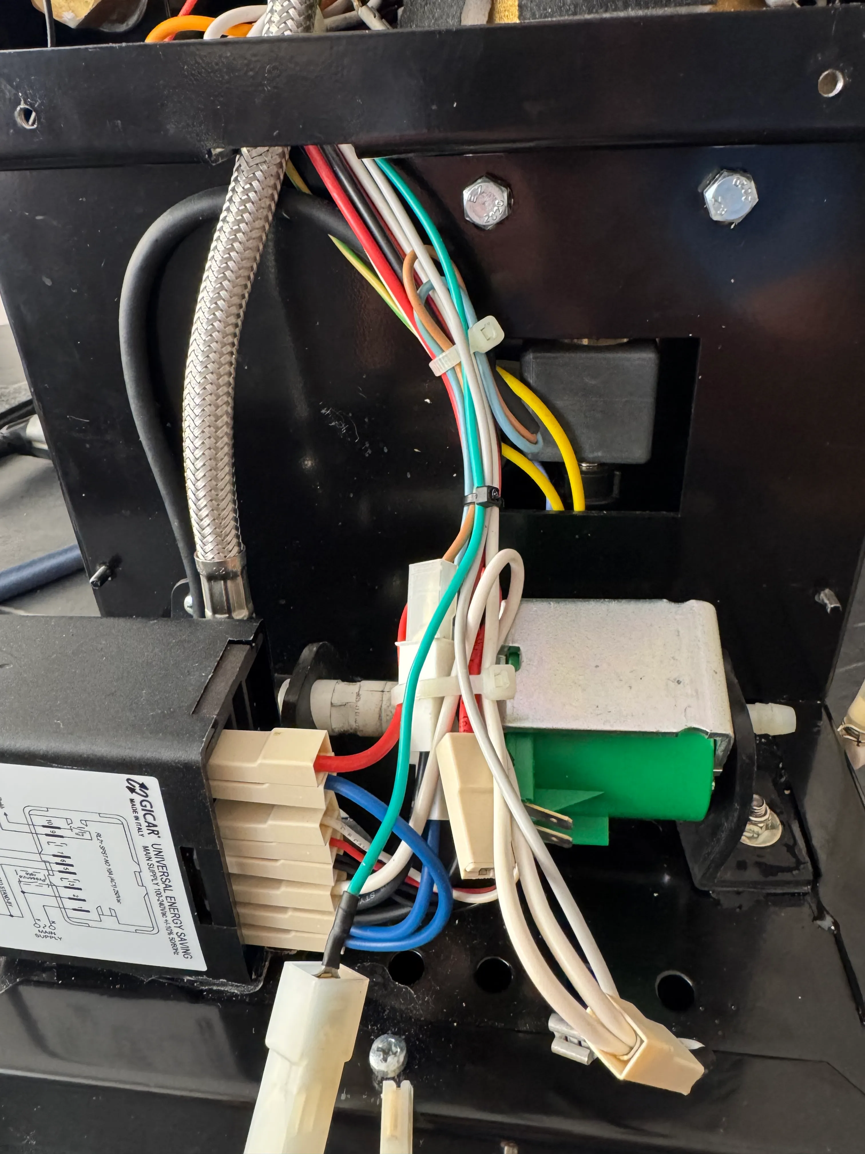
Pump/Three way valve
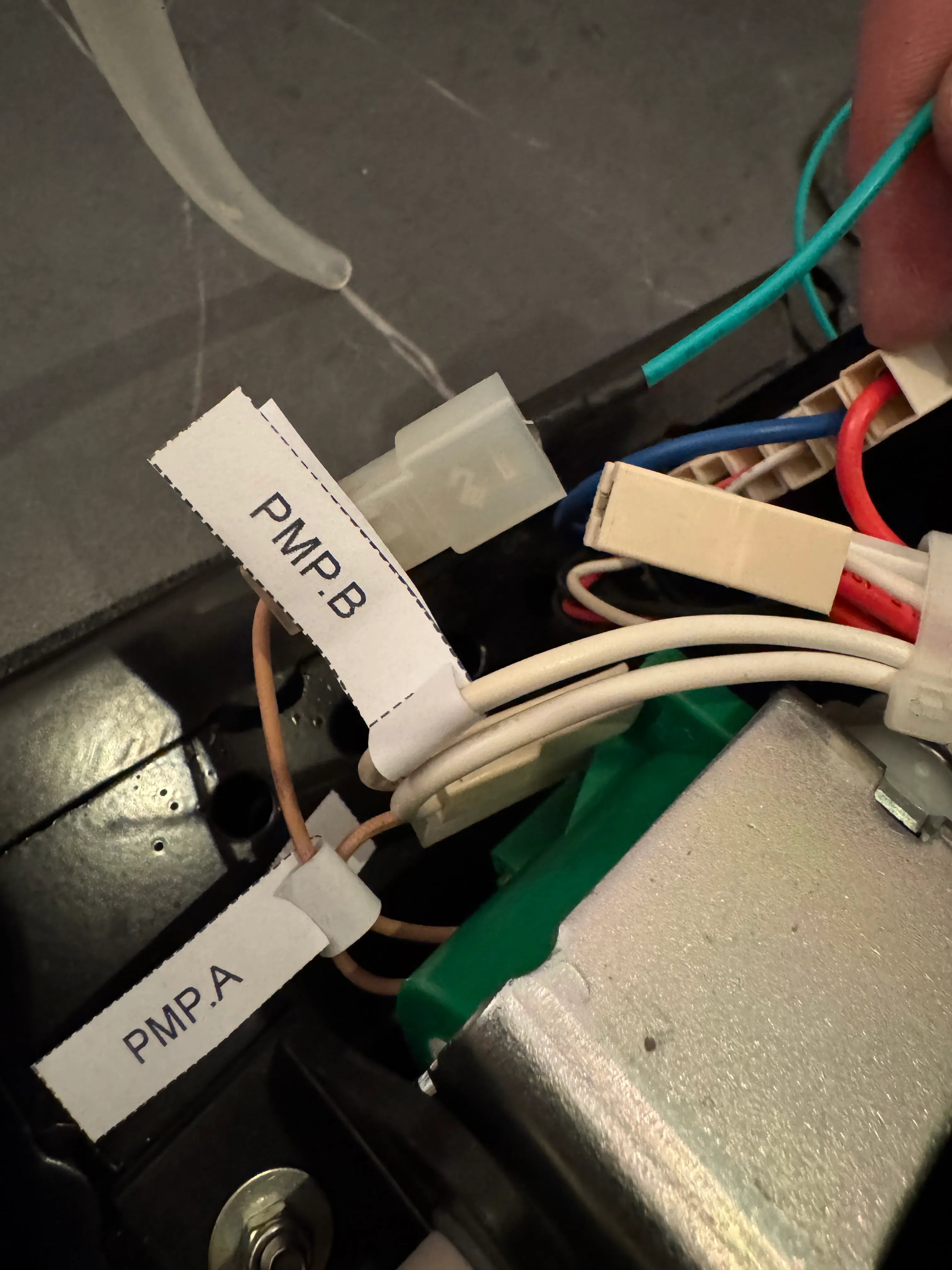
Disconnect the wire PMP.A. This wire will either be connected to a thermal fuse or directly to the pump. If you have a thermal fuse, disconnect it before that. Connect the green cable from the wiring kit to this connection. Run the green cable to the P port of the PCB.
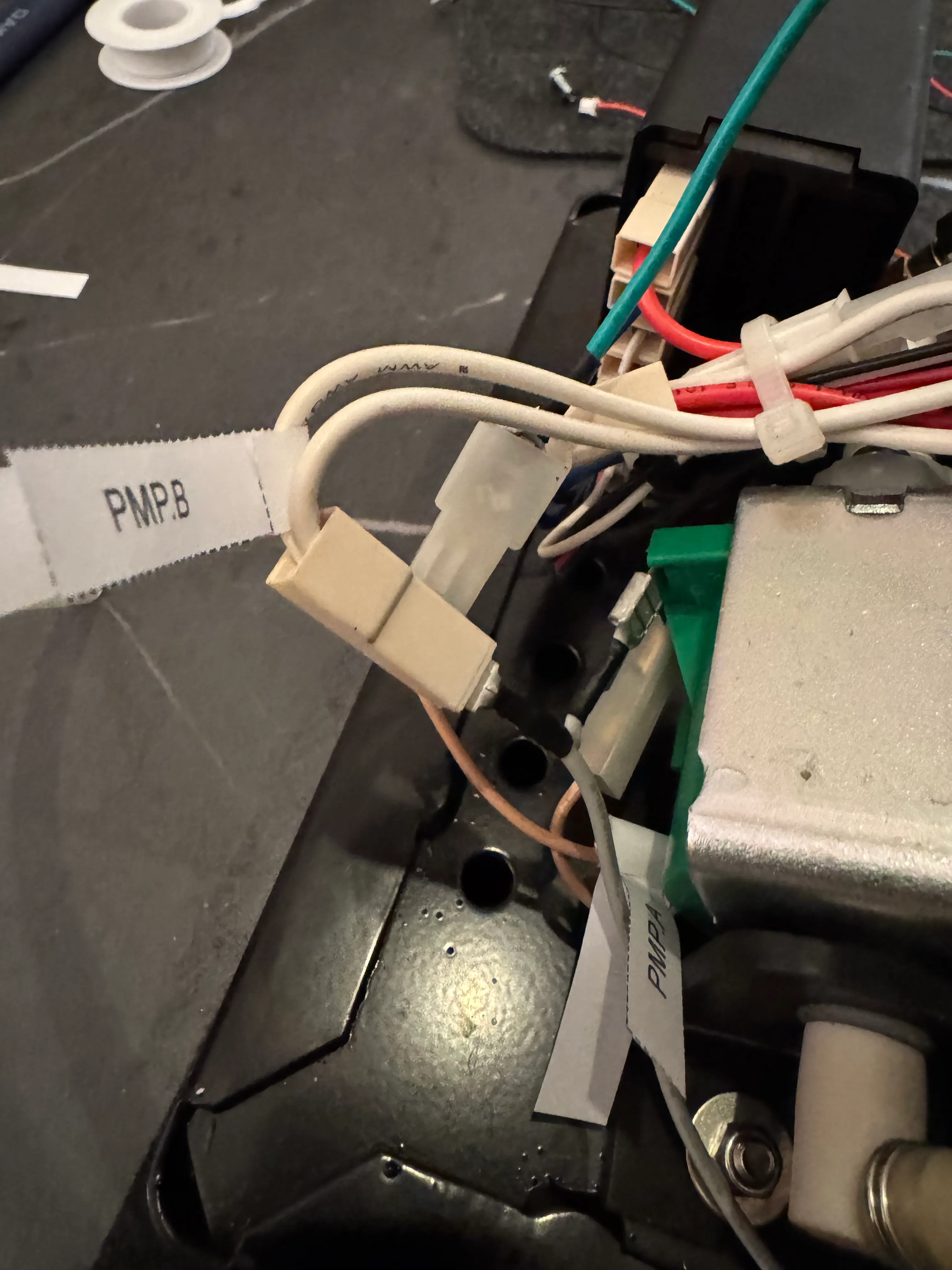
Disconnect the wire PMP.B from the pump and use the grey wire from the wiring kit to piggy back off of this connection (one end at PMP.B, one end at the pump) and run it to the N port of the PCB.
5. LV Wiring
Button functionality
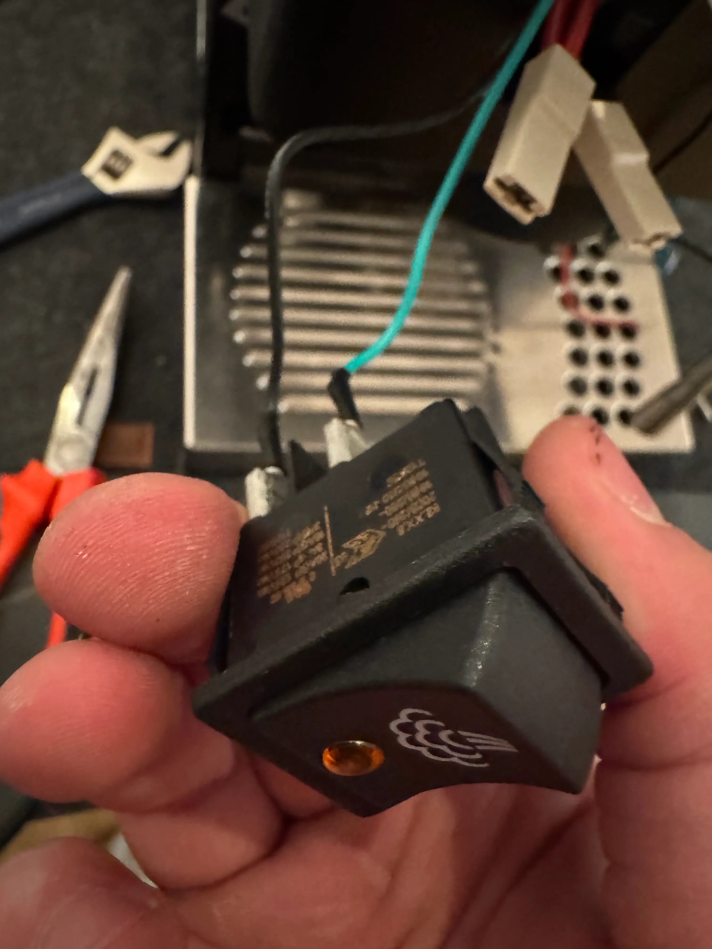
You can choose to retain the functionality of the buttons by using the green/black 4-wire cable from the wiring kit. Connect a green and black wire (check the pinout for steam/brew) to the Brew and Steam switch. Make sure to remove and isolate all the wires from the steam switch before. The green wires should go to where you removed C.2 and S.1, the black wires to where you removed C.4 and S.3.
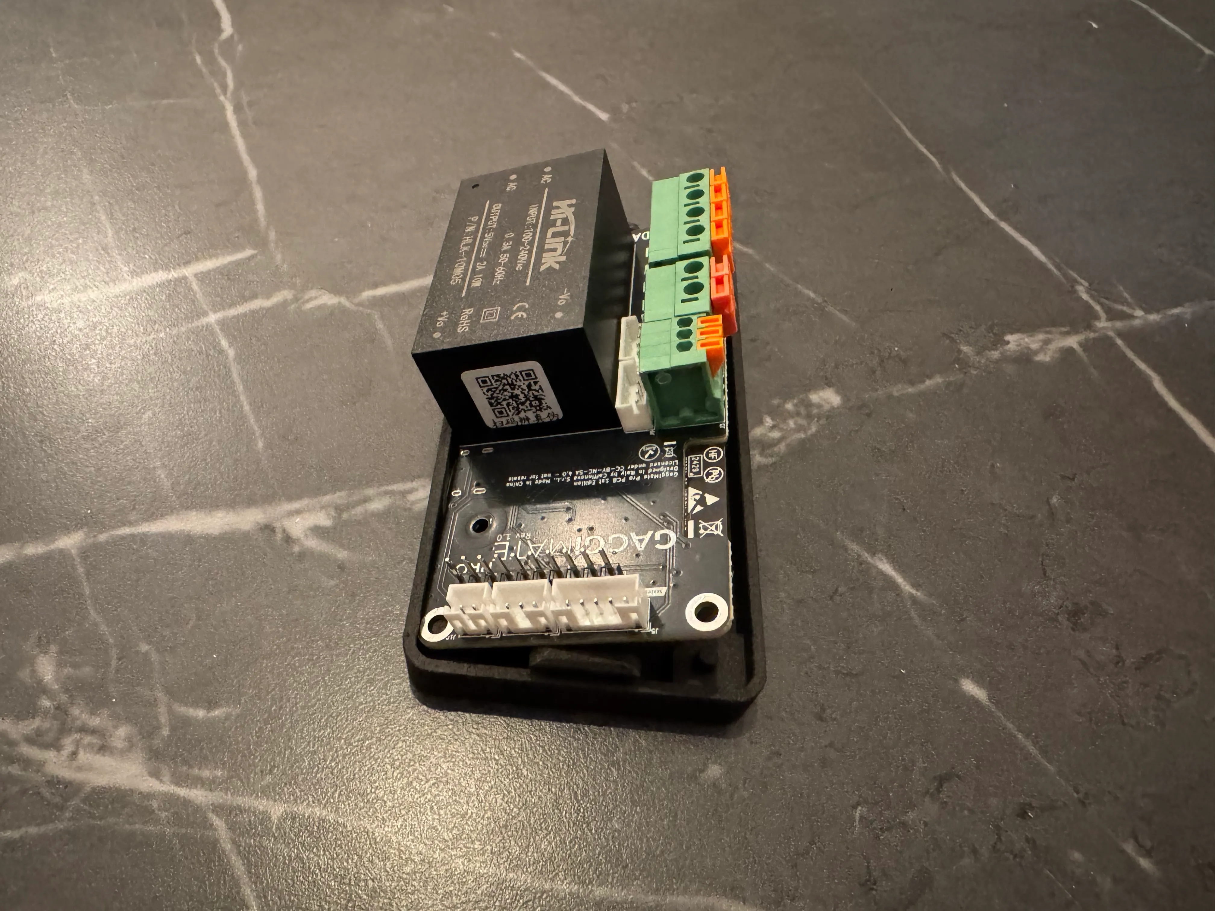
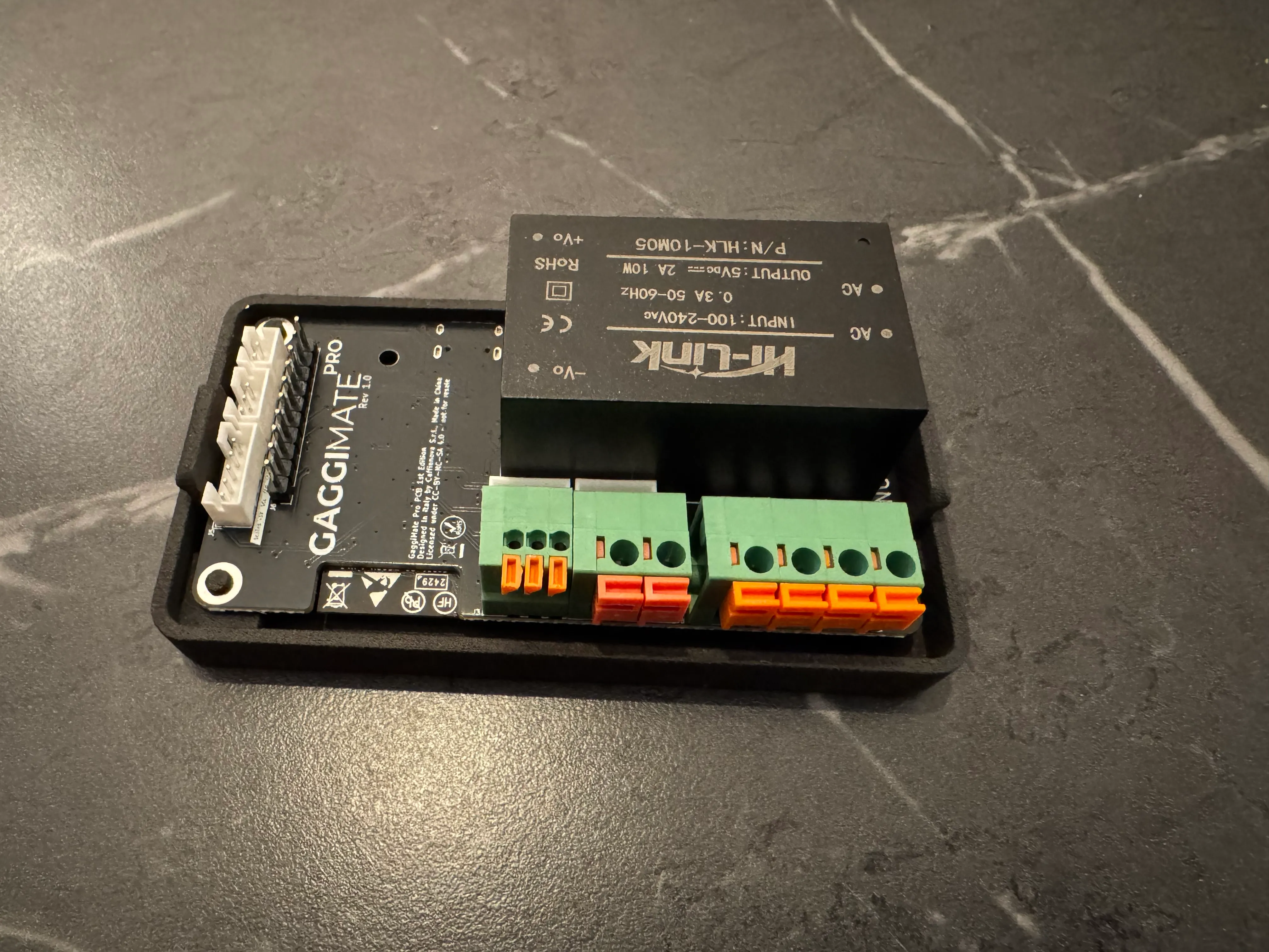
PCB
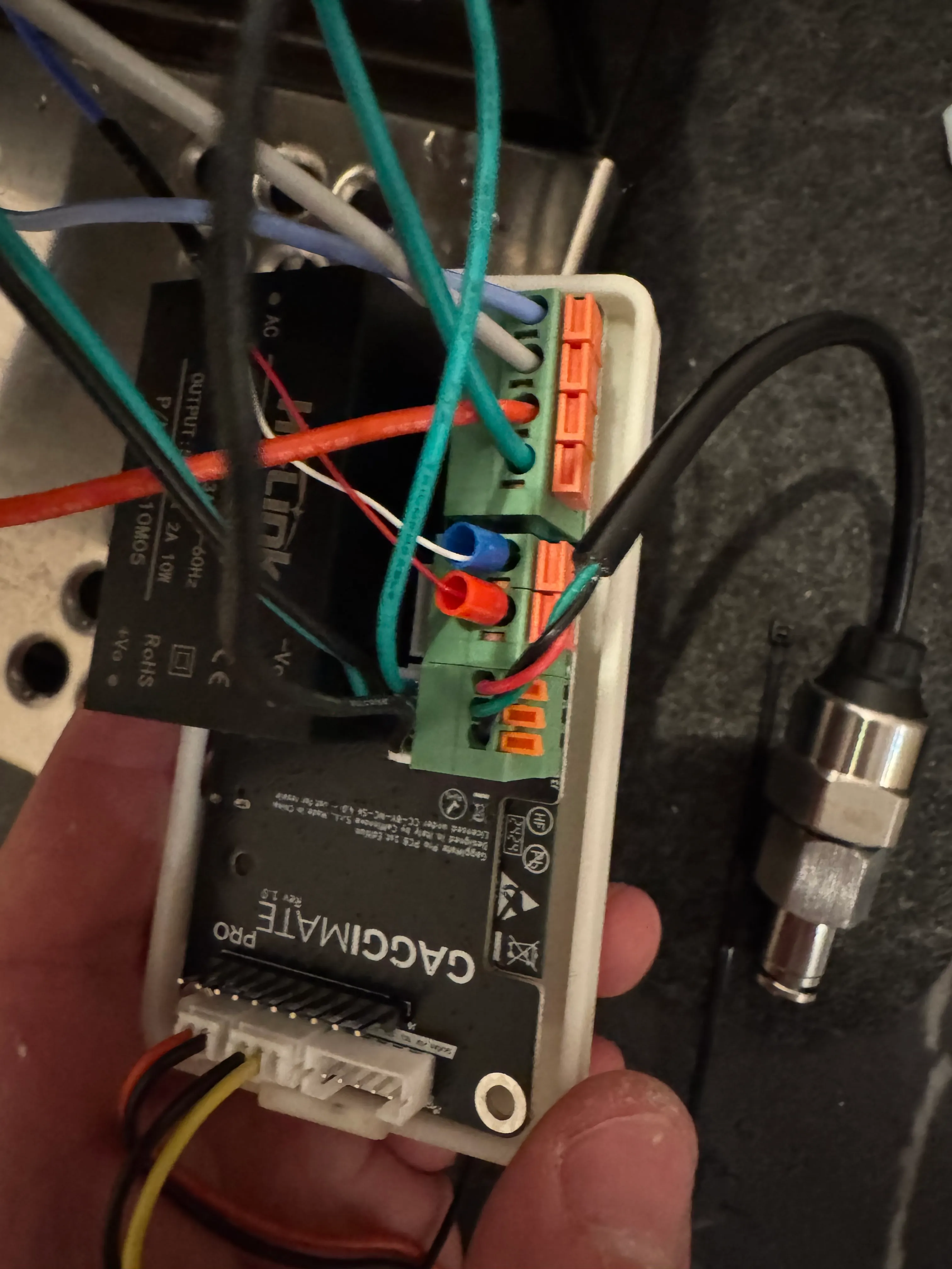
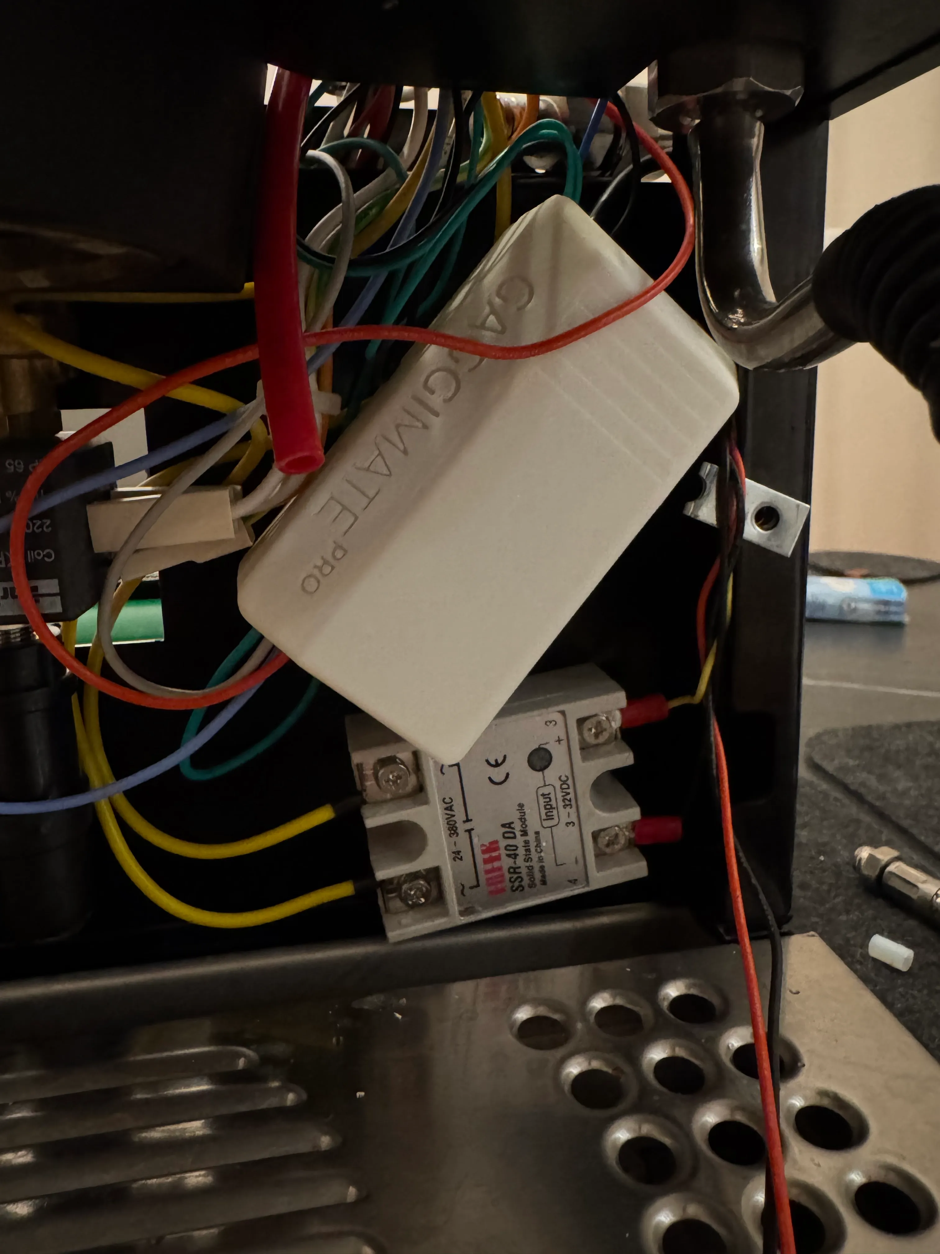
Connect all the wires to the PCB like in the picture and place it on top of the SSR at the front of the machine. Make sure there are no wires underneath the casing or the front panel won’t fit. Run the display power cable out the top of the case.
If using rev. 1.1 of the Gaggimate Pro, the PCB connector for the pressure transducer will have four openings, rather than three as pictured above. Facing the PCB connector from the side with orange levers, the pressure transducer connects as follows (left to right): Black (ground), Open (no connection), Green (analog in), Red (+5V).
Screen
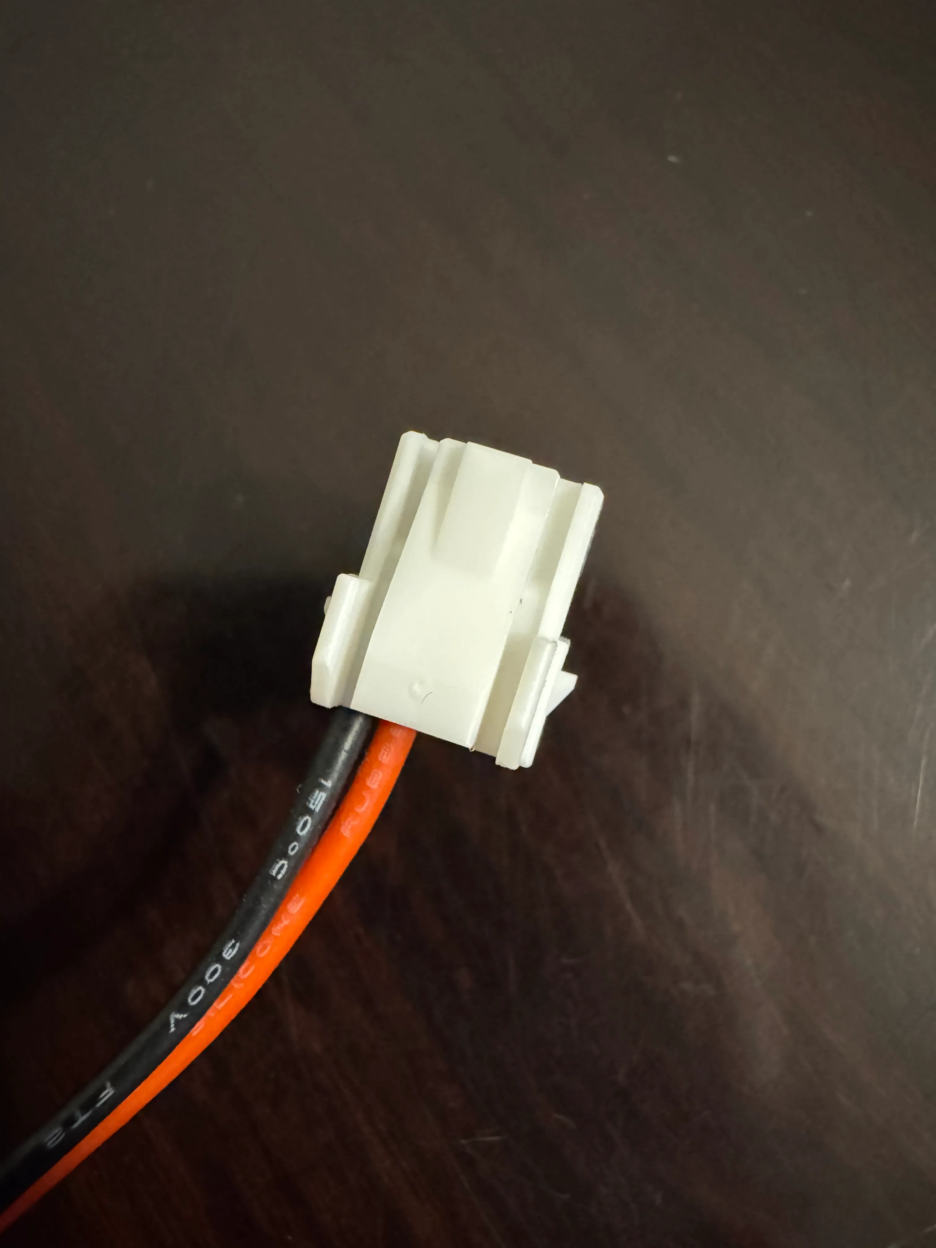
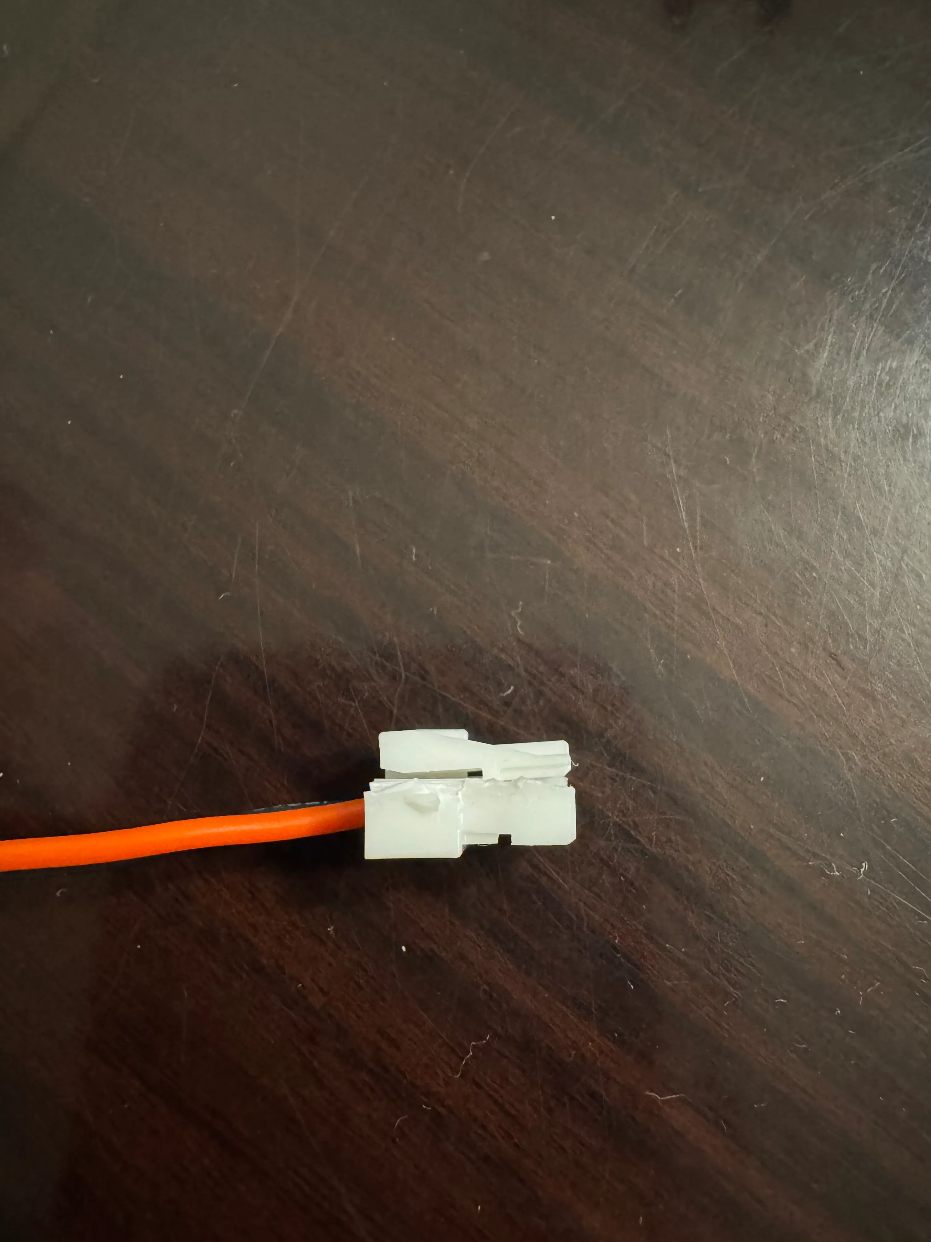
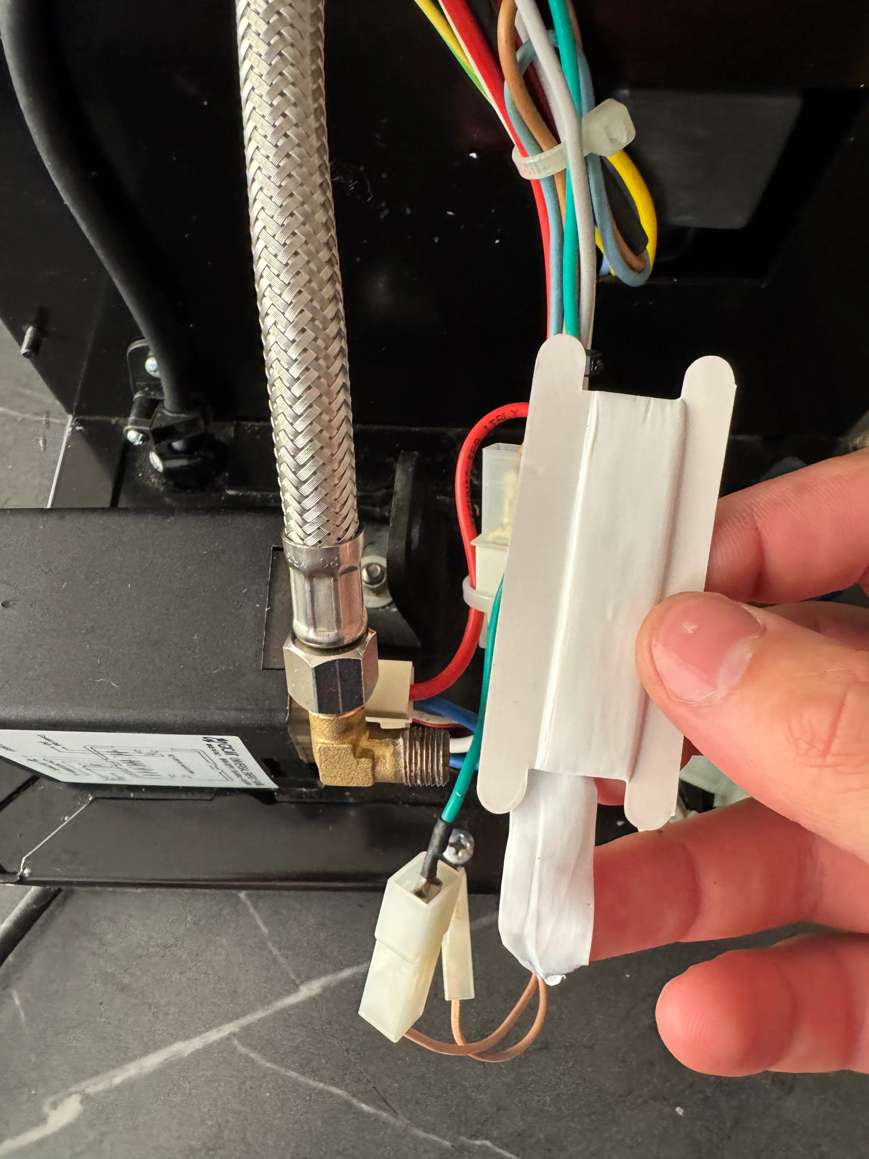
Run the red/black cable from the PCB to the screen and connect it to the 4 pin connector. The cable has enough space to be routed between the cup warmer and casing. The screen casing simply sits on the edge of the housing.
Some generations of the kit came with a slightly mismatched connector. This can be fixed by cutting off one of the side rails of the plug as shown in the pictures below. Make sure not to force the connector into the screen as you may damage it.
6. Plumbing / Pressure installation
Follow this part only if you’re installing GaggiMate Pro.
6.1 New Plumbing (installation at pump)
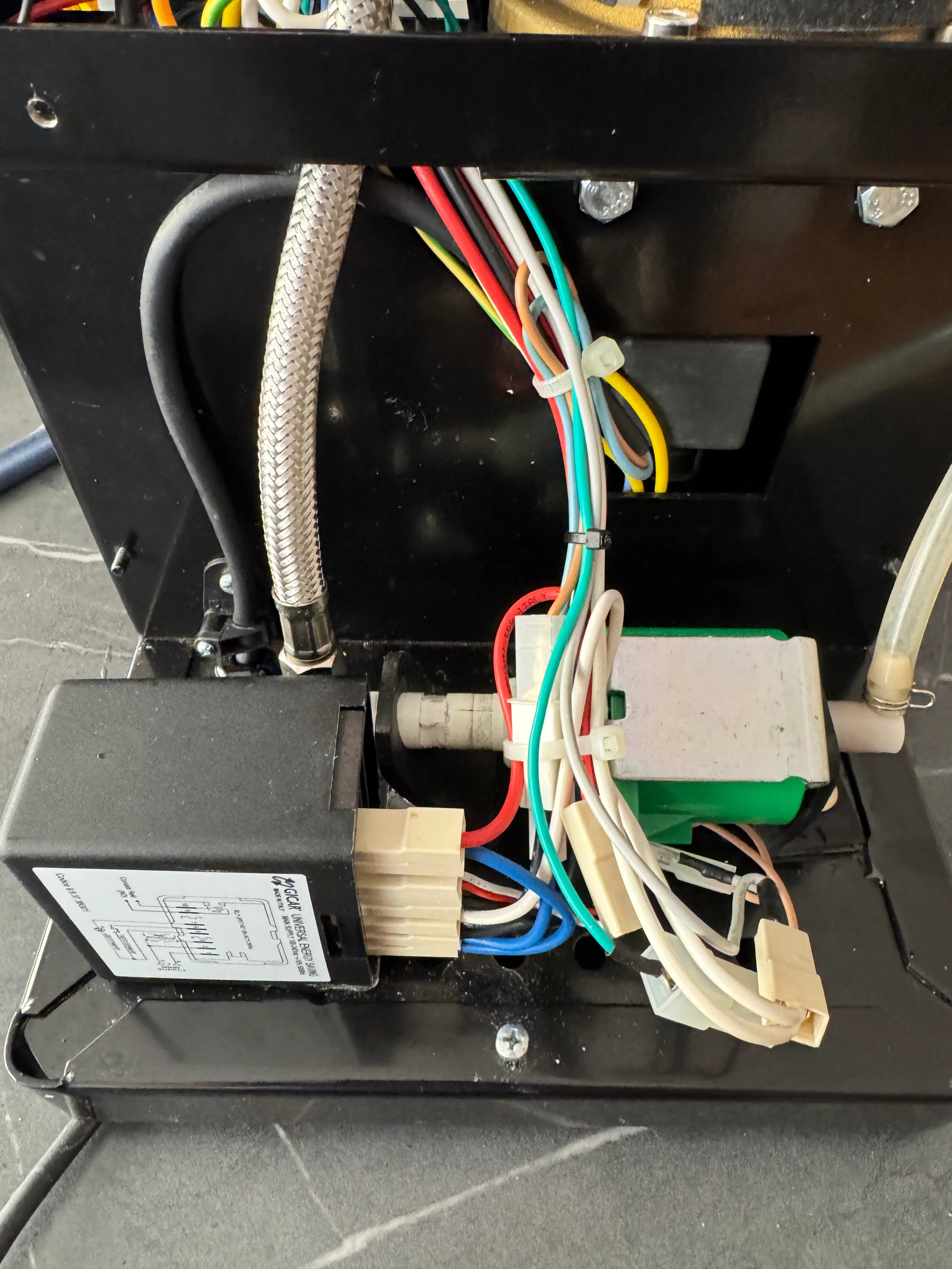
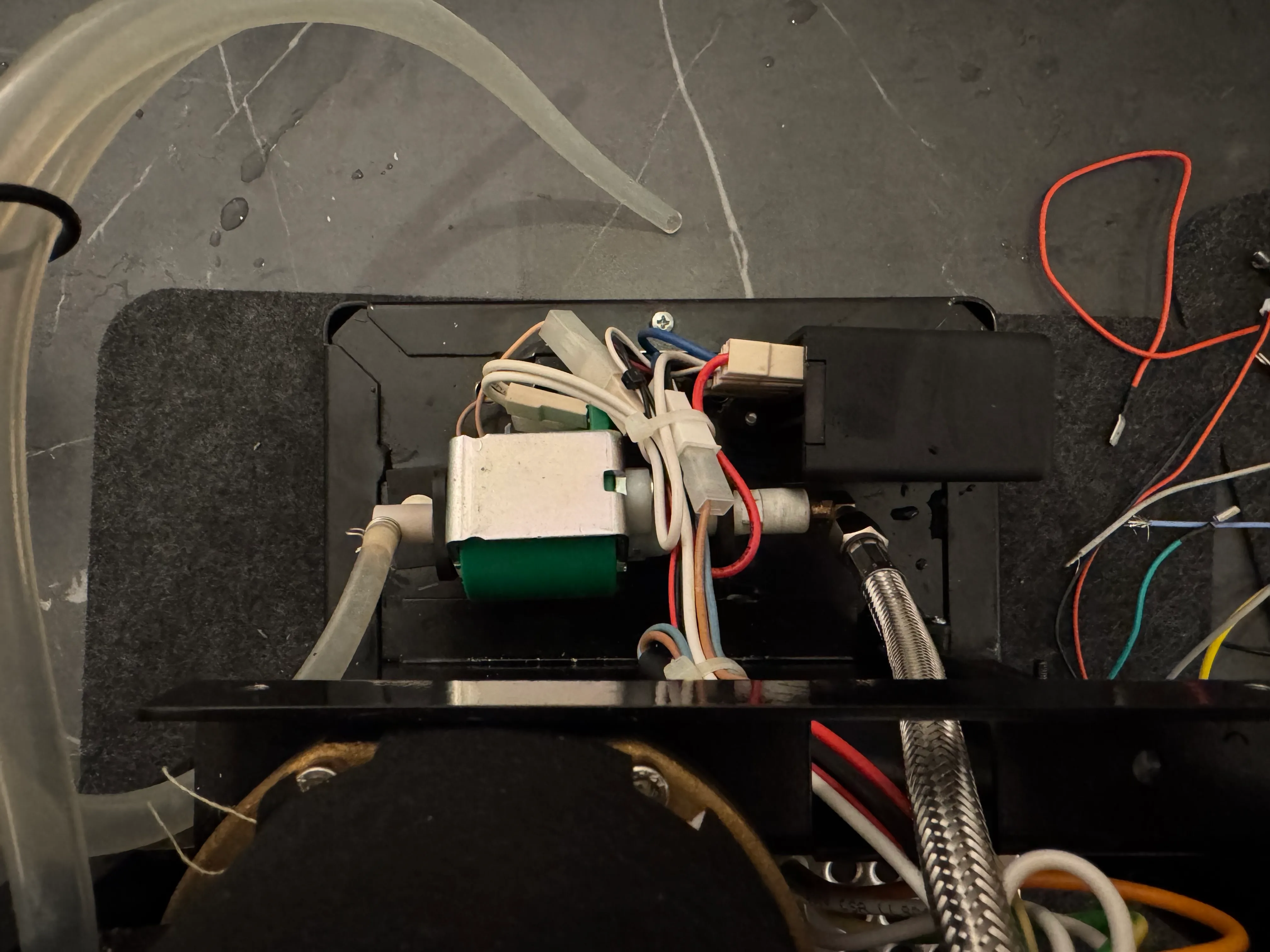
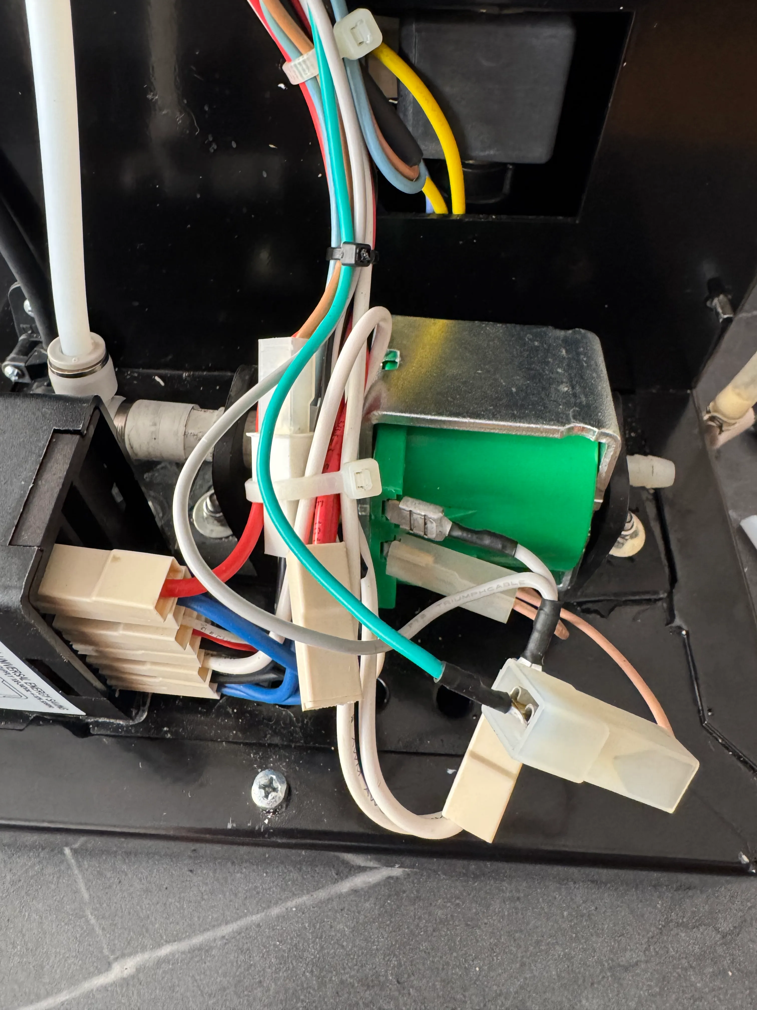
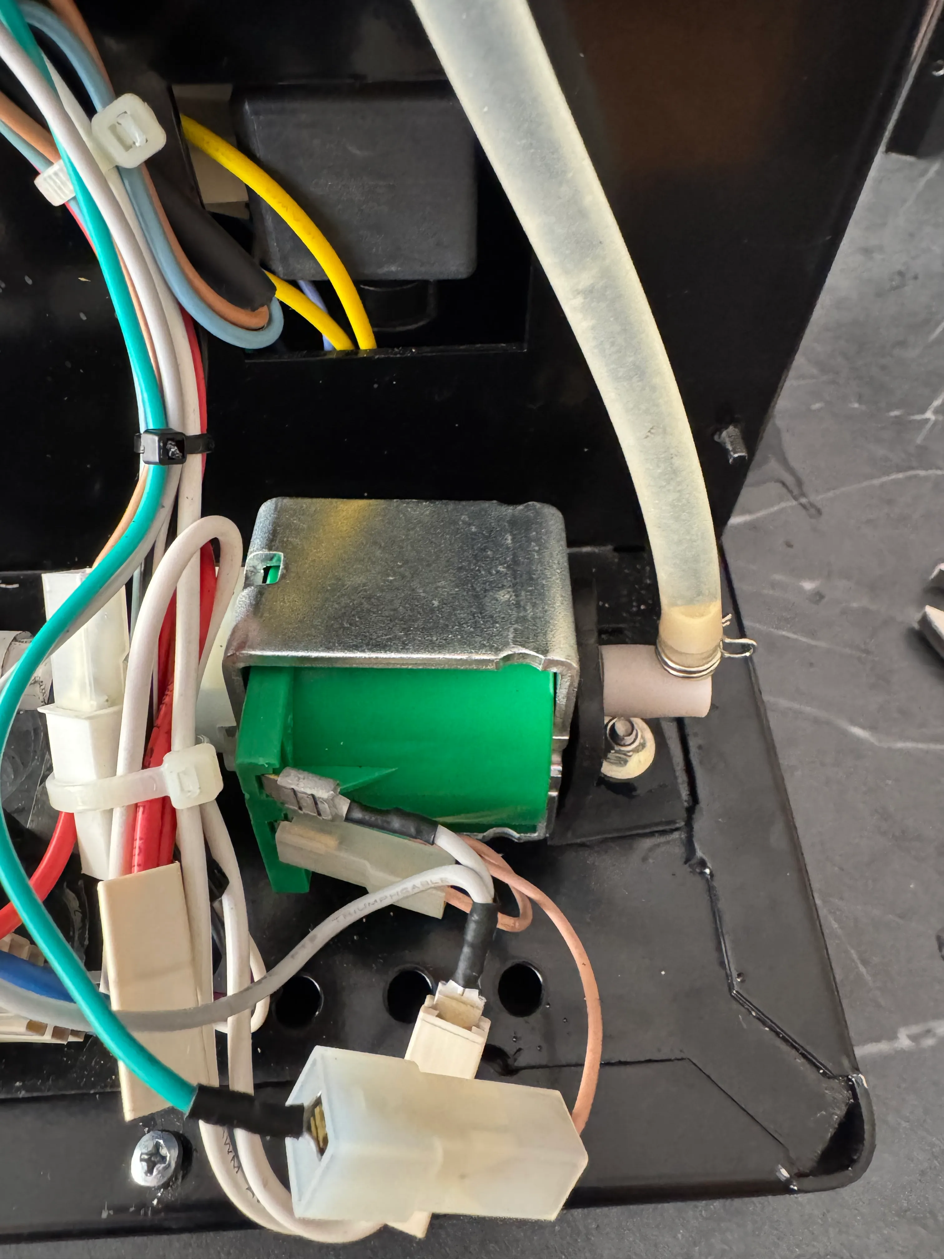
Turn around the machine so you’re looking at the pump then disconnect the cables from the pump. After that’s done, also disconnect the suction tube from the pump as shown above.
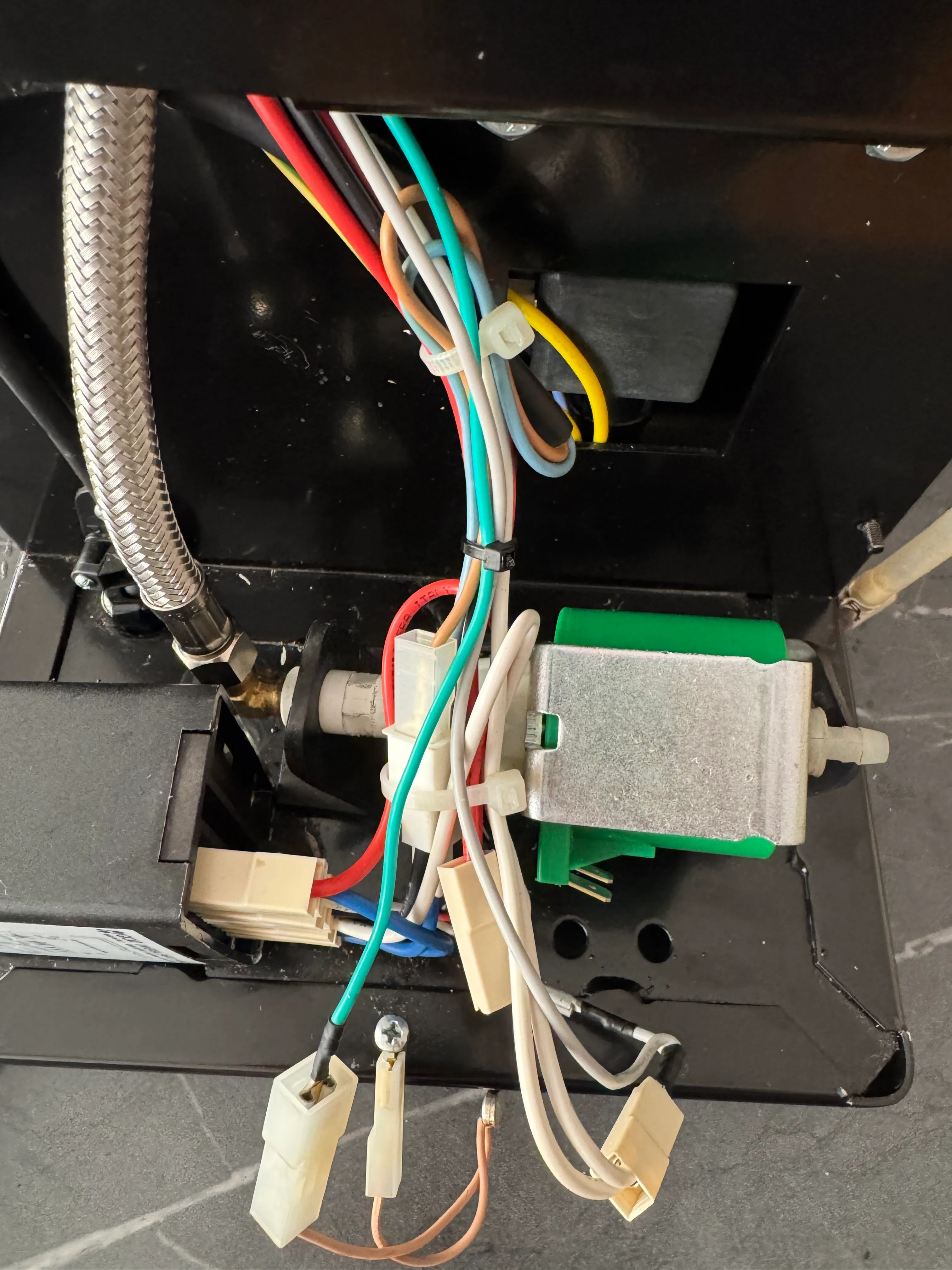
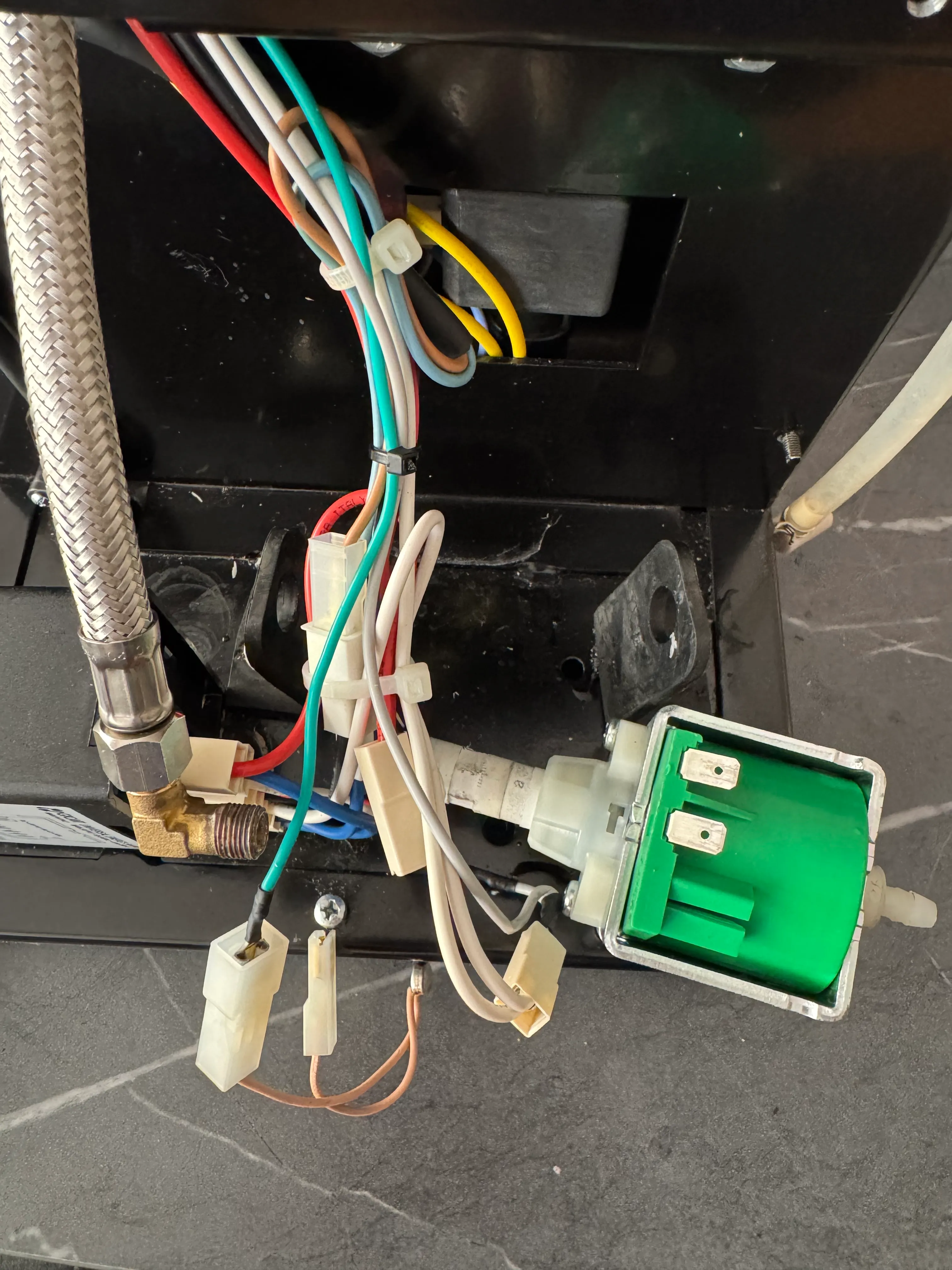
Take out the pump from the right rubber mount and unscrew it from the L-fitting. Your pump should now be completely free.
Put 4–5 rounds of PTFE-Tape clockwise onto the L-fitting. This will make sure your connection holds pressure.
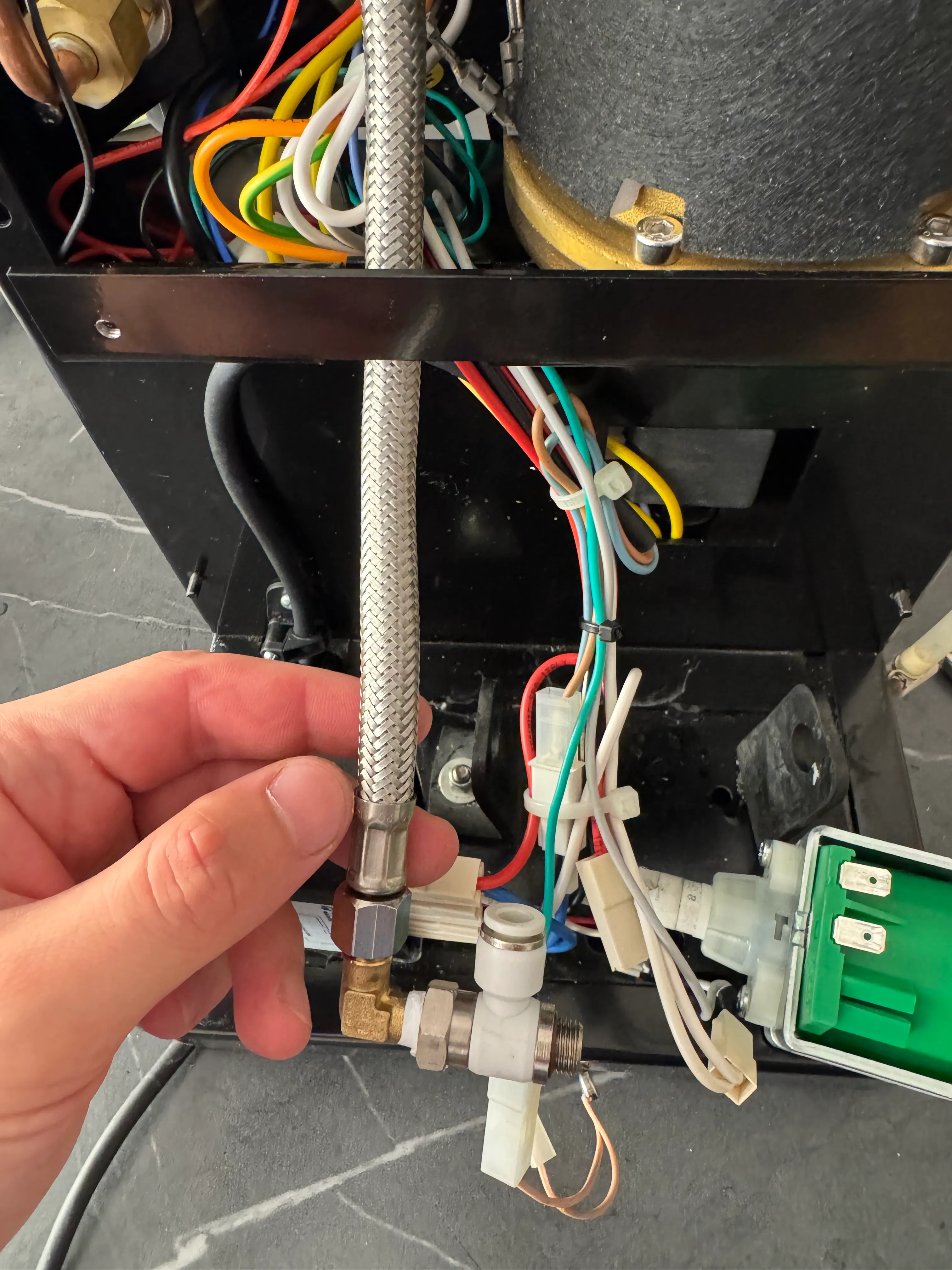
Screw on the T-fitting from the kit onto the L-fitting making sure it’s tight. The white part can be rotated around so the position doesn’t matter. Once this is done, you can screw the pump onto the new fittings.
Make sure you thread the pump back through the rubber mount before.
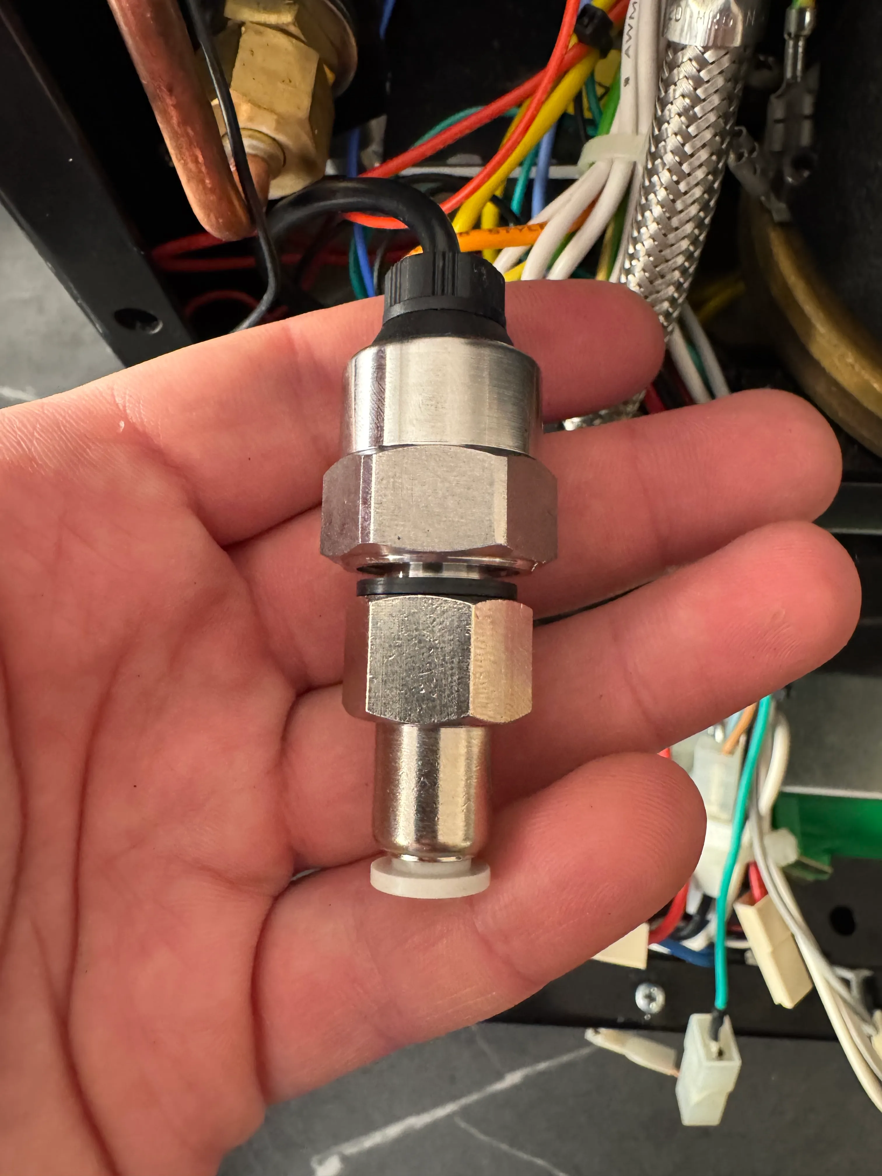
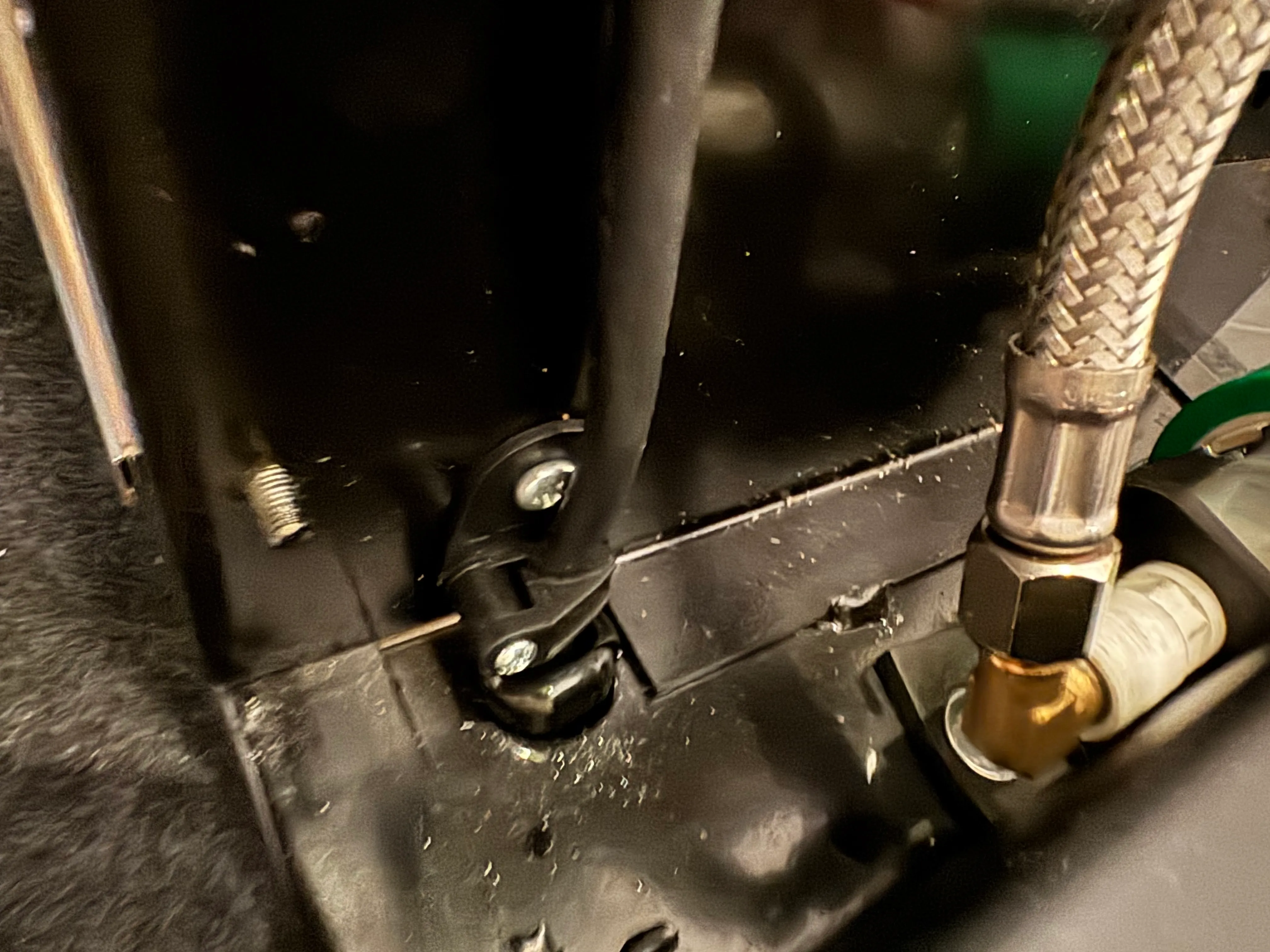
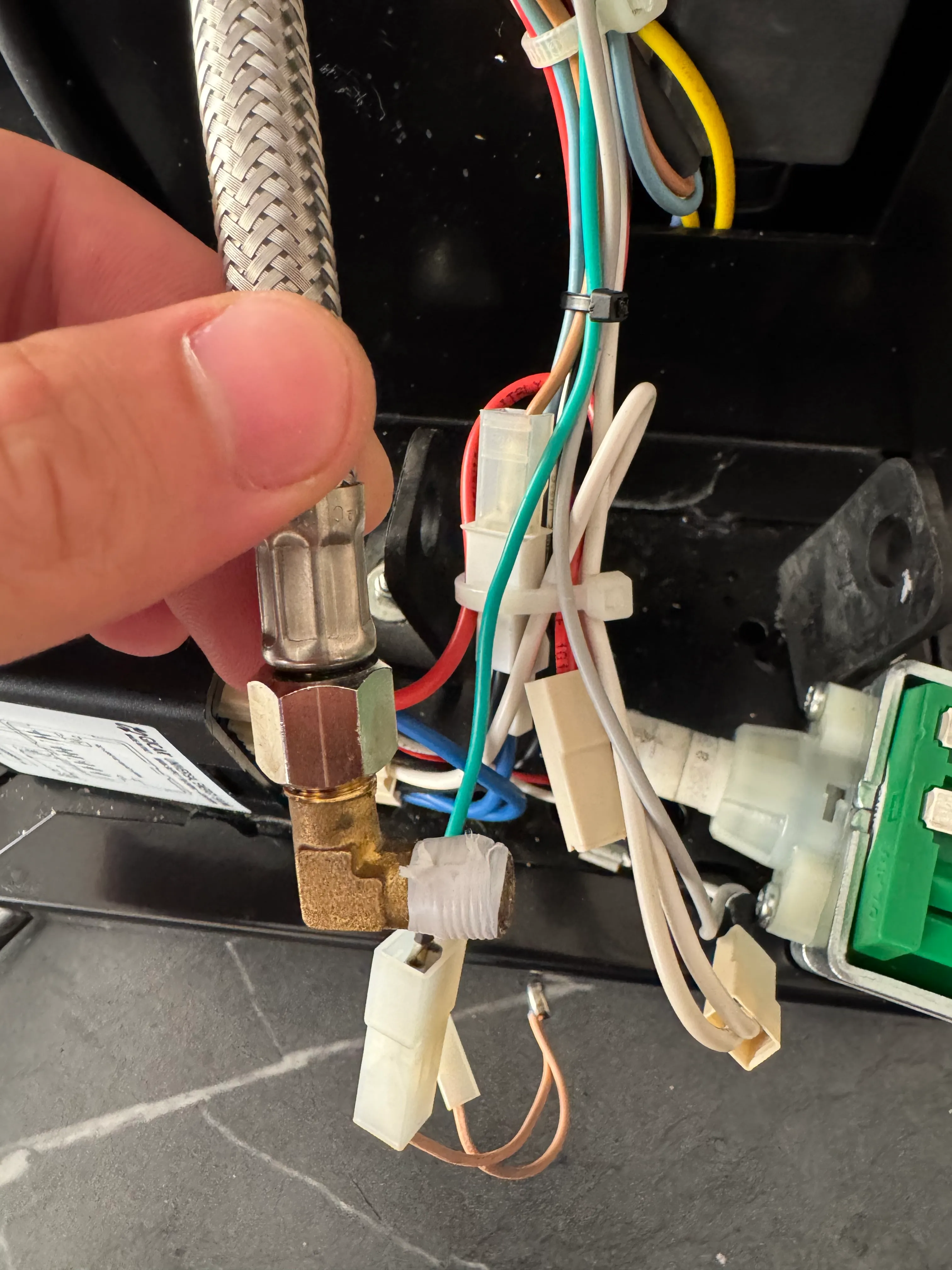
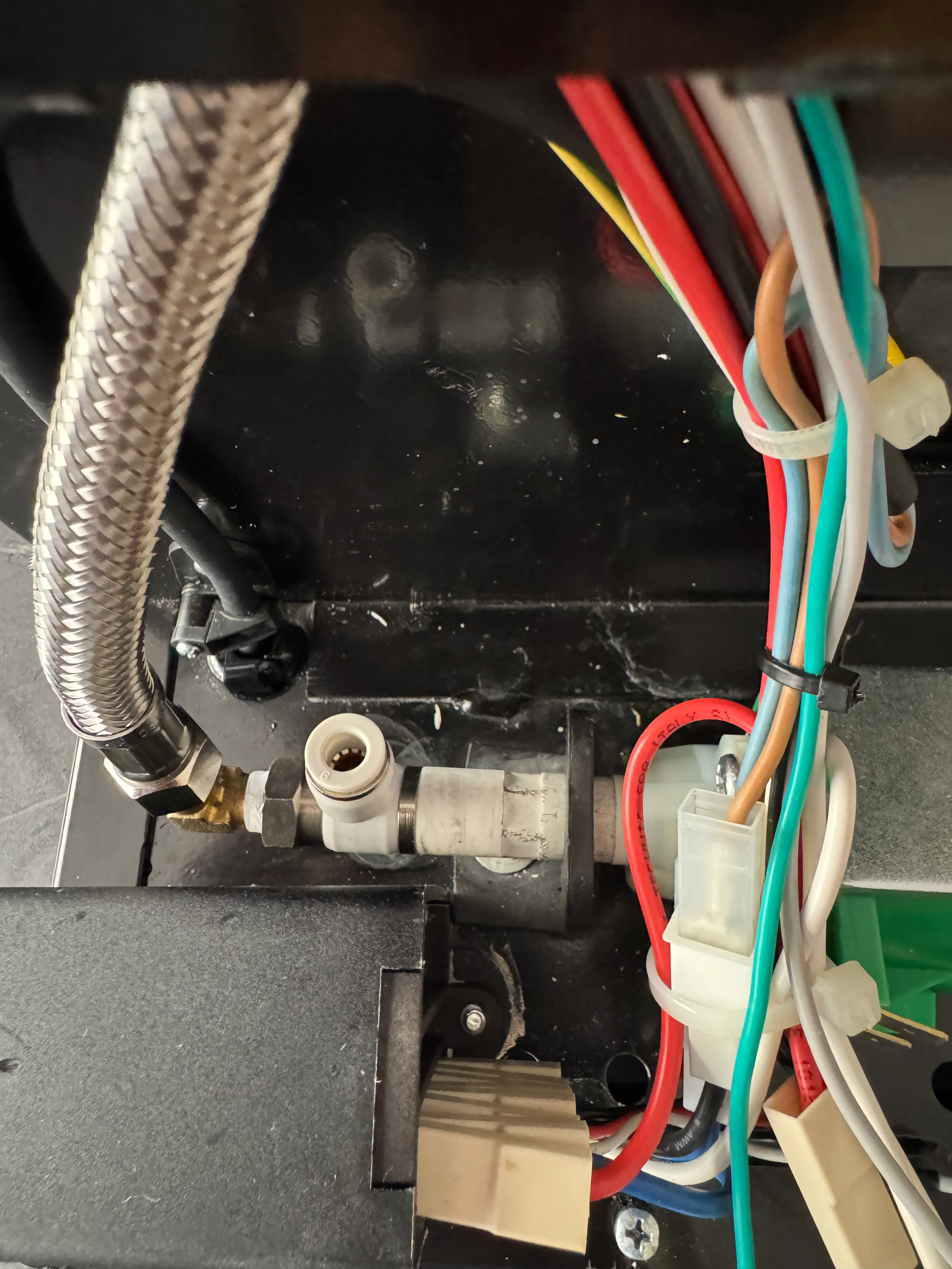
Screw the G1/4 PTFE fitting onto the pressure transducer - this should only be hand tight but tight enough to hold pressure - and place it between the steam valve and boiler.
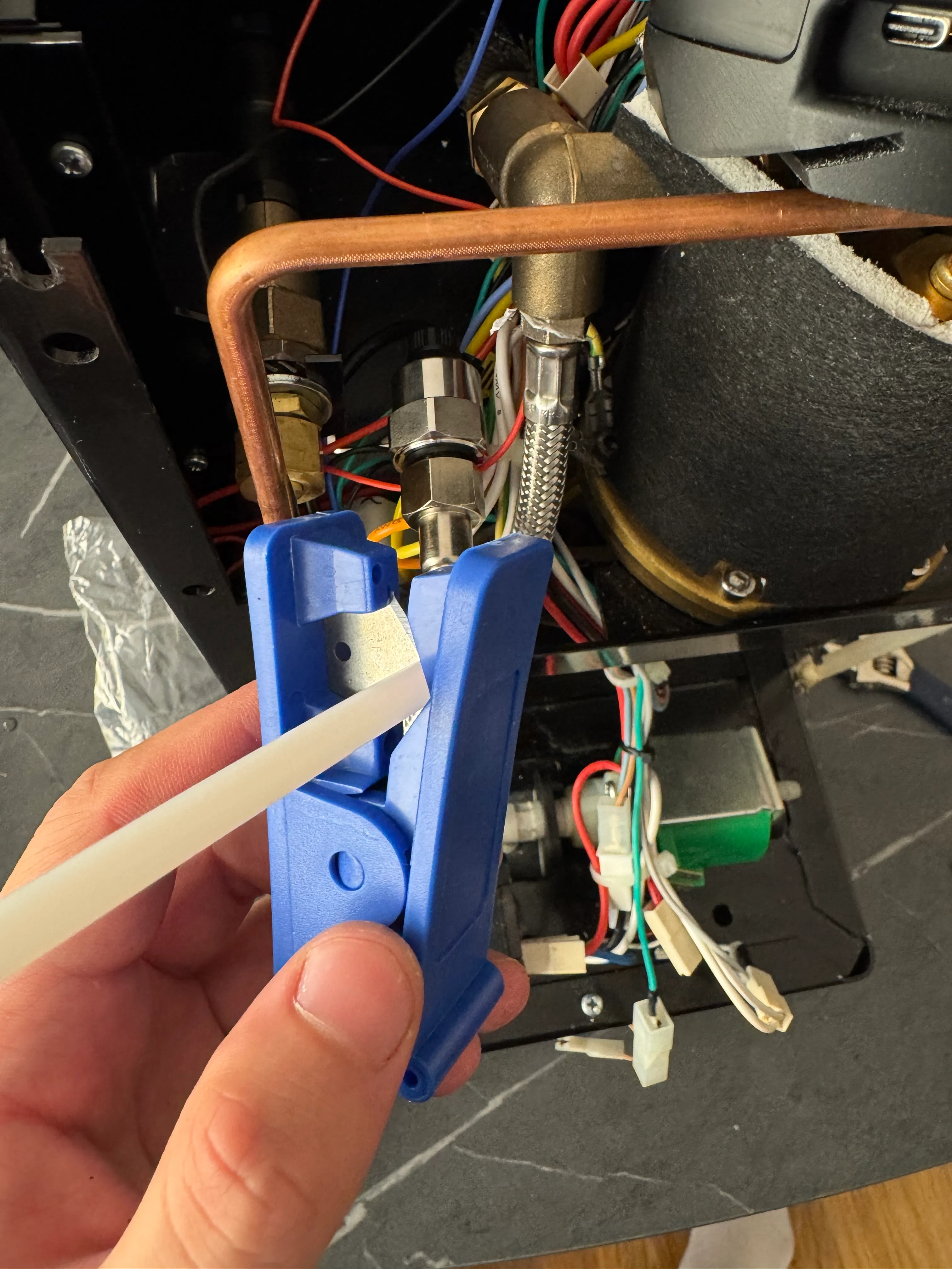
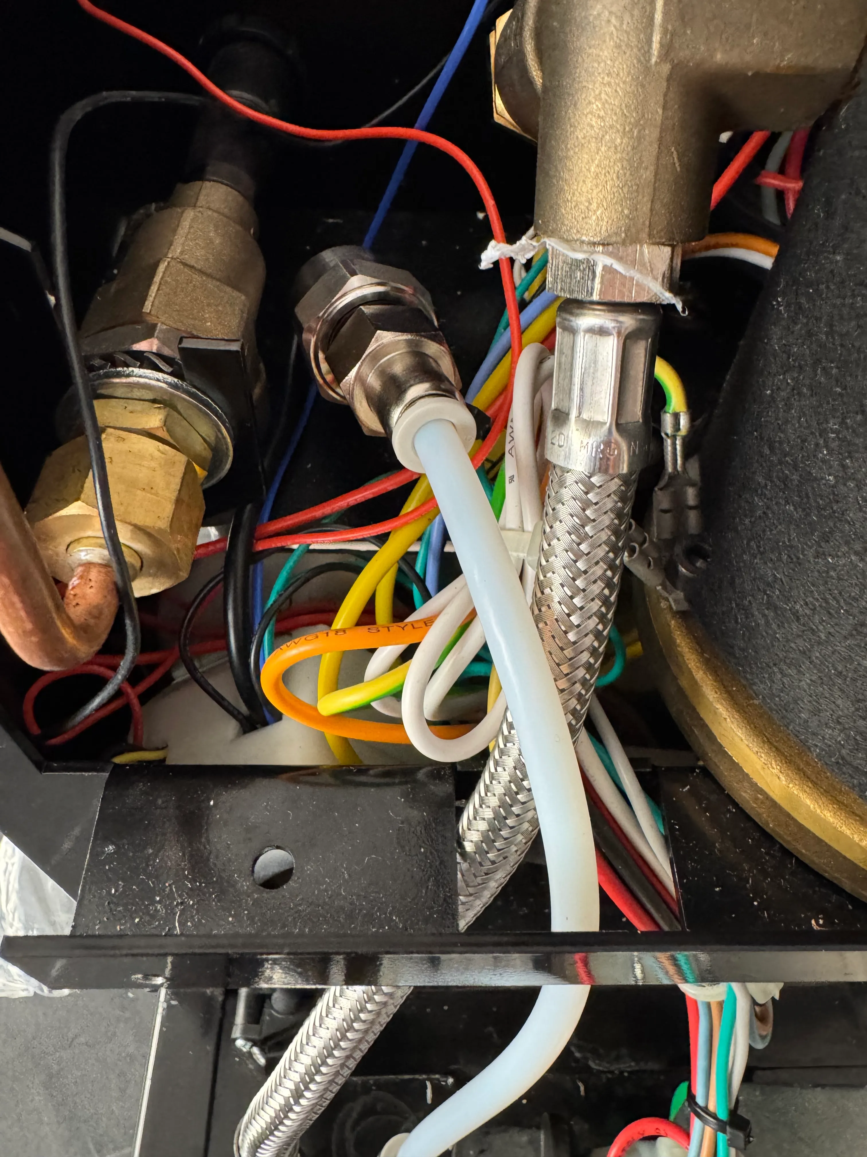
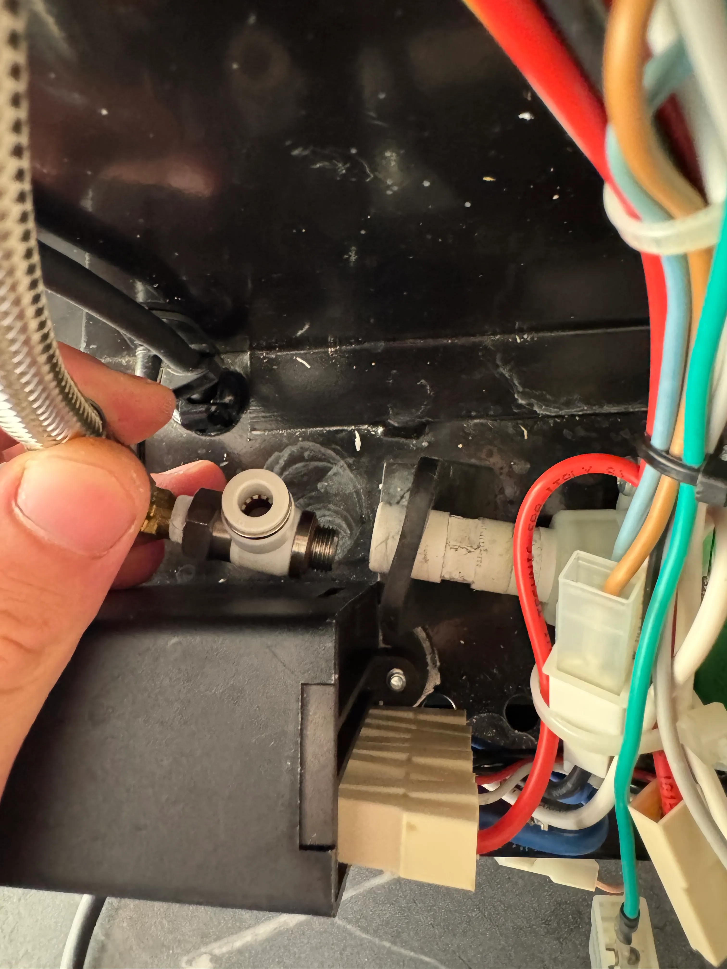
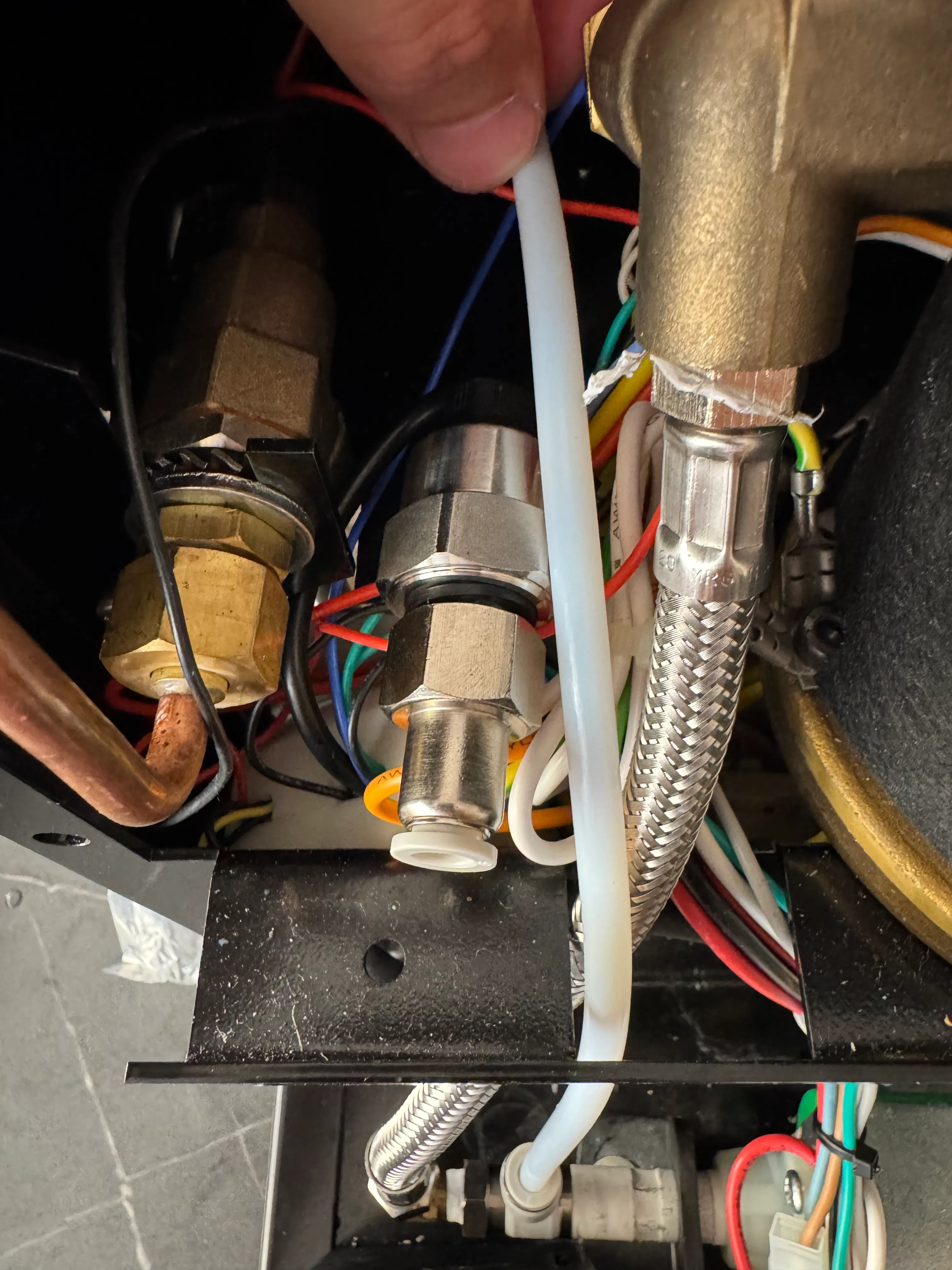
Plug the PTFE tube into the fitting near the pump and measure out what length you need to your pressure sensor. Use the included cutter to cut it to length. Fill the tube with water and connect it to both the T-fitting and the pressure transducer.
Finally, reconnect the wires to the pump as well as the suction tube. Also connect the pressure transducer to your PCB as shown above. You have now installed the plumbing onto your machine.
6.3 Pressure test
Before you close up the machine you’ll want to run a pressure test of the system to catch any leaks. For this you can simply run the water mode for a while and see if anything needs fixing. If there’s no leaks at room temperature, try again at brew temperature.
7. Finishing steps
Review all your labeled connections for accuracy and completeness. Ensure that there are no exposed wires and that all connections are secure and insulated.
Once you have completed that step, test your wiring for possible shorts with a multimeter and make sure you haven’t connected any LV connections with HV connections. Also test the switches operation for continuity in the different switch positions.
Testing
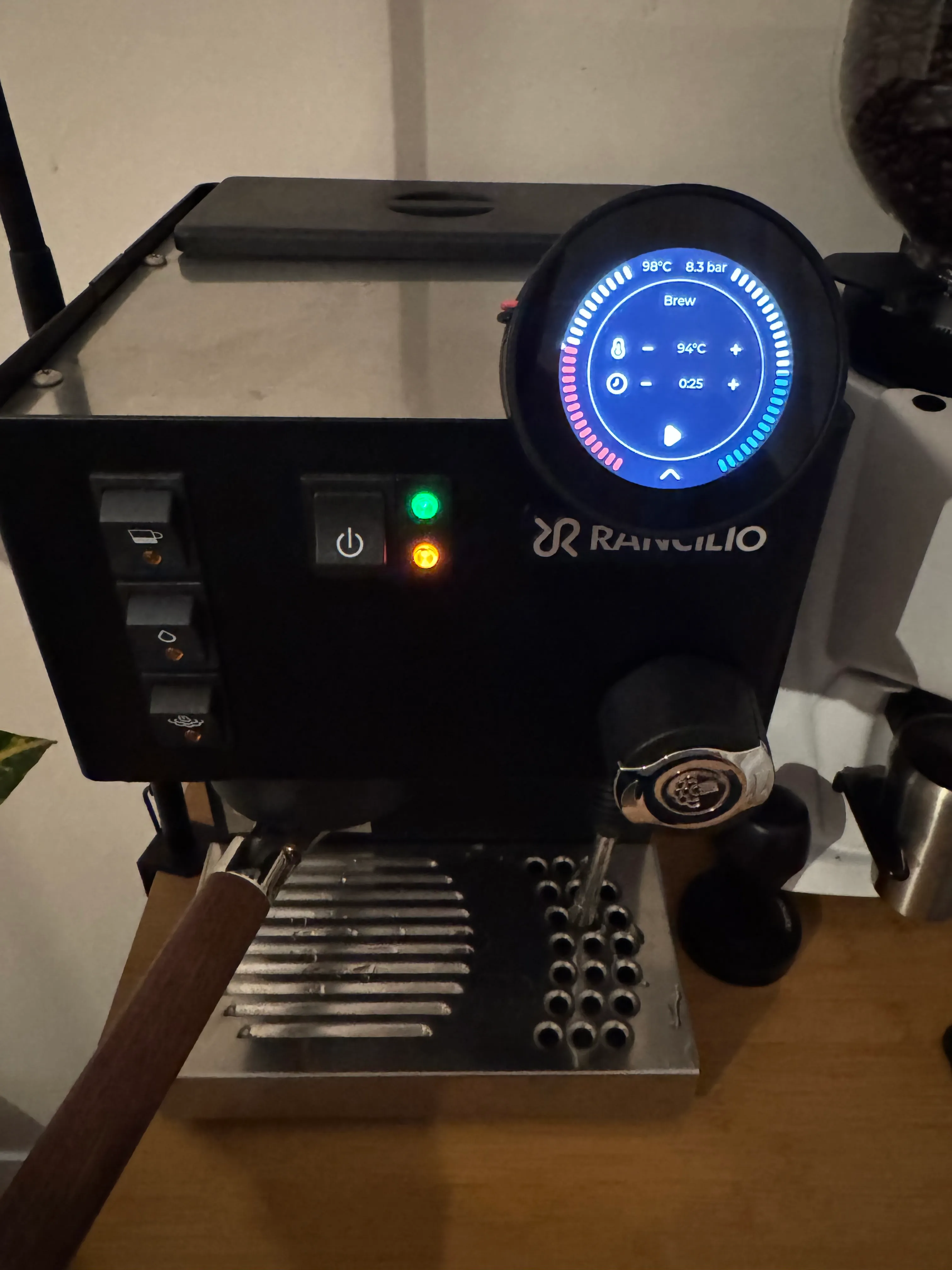
Now is the big moment. Turn on your machine for the first time. The heater should not be heating on power-on and nothing else should be running. You can check if the heater is doing anything by observing the LED on the SSR. The screen should turn on and show the Standby screen of GaggiMate. Touch the screen once to switch to warmup mode, you should see the current room temperature being displayed and the LED on the SSR will light up indicating it’s heating up. Check that nothing is leaking inside of the machine.
Final Steps
Reassemble the Machine: Carefully put the panels back on, ensuring that there are no pinched wires.
Important: Conduct a Safety Check: Perform a final inspection to ensure everything is insulated and that there are no exposed wiring connections.
If you have any further questions or need additional clarifications, feel free to go into the Discord and make a help thread or post on our Subreddit. Please also check out the Troubleshooting guide.
Congratulations
You have now finished setting up your Gaggia Classic Pro with GaggiMate and can start making coffee. To check more tasks on your first startup go to First Start. When you do the first test shots and check the system, remember that you’ll need to have a puck or blind filter in the machine to build any pressure. If you encounter any problems during the installation check our Troubleshooting guide or open a help thread in #gaggimate-help on Discord.
Have questions?
Still have questions? Join the Discord!