A comprehensive community-driven guide for modifying, upgrading, and maintaining DeLonghi ECP and Stilosa espresso machines.
Community Guide
This guide is a community guide which is not maintained by GaggiMate. The author is not affiliated with GaggiMate.
Author: Jay R. (Jayblah) Last Updated: April 11, 2026 Credits: Flavius, mdwasp, TorxFighter, Abunchahicks, odor4fun, Prowler, Stuart, and the entire GaggiMate community for their contributions to this guide and the project as a whole.
Important Notes
High Voltage Safety: Exercise extreme caution when working with high voltage. If you are unsure about any steps, consult a professional technician. Follow Local Codes: Ensure that your work adheres to local electrical codes and standards. Documentation: Keep a record of your wiring setup for future reference and troubleshooting.
If you see any errors or have any suggestions on making purchasing cheaper or easier for people, please join us in the GaggiMate Discord channel.
This is a major modification requiring a full rewire.
Rewiring: You will remove most existing wiring and create a new harness to connect to the GaggiMate PCB.
Controls: The stock rotary knob will be removed. The machine will be controlled entirely through the GaggiMate interface.
Power: You will install a new 3-prong plug for the American model.
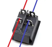
ECO Mode: This process disables the stock “ECO Mode” found on EU models. You will replace the existing power switch with a 4-pin on/off switch.
While not a “simple” mod, it is manageable if you are comfortable with basic hand tools and confident following detailed instructions. This guide assumes you have purchased the specific items listed below and is not suitable for a “LEGO” style build.
A Note for the Pros
While this guide provides a tested, reliable path for the ECP, the GaggiMate system is highly adaptable. If you’re an experienced tinkerer, feel free to innovate and be sure to share your ideas with the rest of us!
A Note on the Stilosa and the EC-702
This modification is compatible with the Stilosa and the EC-702. The latter might actually be the best platform for the modification due to its build quality and spacious internal capacity. The only significant difference is the screen housing, which will require a different print. All images and references below feature the ECP, but the process is basically identical for the other models.
Video Guide
Thanks to hard work of Prowler, we now have a wonderful video guide to also accompany this written guide! It covers the entire process from start to finish, and is a great resource to have on hand while working on your machine.
DeLonghi makes several popular, affordable, and surprisingly capable semi-automatic espresso machines. You can often find a well-maintained pre-owned model on Facebook Marketplace or elsewhere for a great price. I paid just $50 for mine. Even in stock form, the ECP and Stilosa can produce excellent espresso. Their stainless-steel grouphead and sturdy internals make them very capable, especially when paired with a bottomless portafilter and a quality grinder.
However, if the idea of installing a Ferrari engine inside a Toyota chassis sounds exciting, this modification is for you. After installing the GaggiMate, these little sleepers can rival the performance and features of $1,000-plus single-boiler espresso machines for a fraction of the cost.
You Can Do This!
Before I started this modification, I had never cut, crimped, or spliced a wire in my life. Despite that, I successfully installed the GaggiMate on my DeLonghi ECP. If I can do it, you can do it too.
Take your time, follow each step carefully, and you will be just fine. Make sure to read through the entire guide at least once before you start working on the machine. This will help you understand the overall process and prepare you for what’s ahead.
Disclaimer
By proceeding with this project, you acknowledge and agree that you perform these modifications at your own risk. The author of this guide assumes no liability for any damage to your equipment, property, or injury to yourself or others. If you are unsure about any step, consult a qualified electrician or professional technician.
Shopping List
Please read this guide in its entirety before purchasing any parts. To ensure compatibility between the GaggiMate and the DeLonghi ECP series, it is critical that you source components that match the specifications provided in the list below.
While the following shopping list includes tools and items designed to streamline the installation, experienced modders should review the requirements to determine which items are strictly necessary for their specific setup. You are welcome to source these parts from any retailer of your choice. The provided links are for reference only, and I do not earn commissions from them.
The most important factor is that the technical specifications of your parts are identical to those listed.
A compatible ESP-32-S3 screen ⚠️ Buy only one screen.
Tools & Consumables
Printed Parts
We recommend printing all parts using PETG or ABS for durability and heat resistance. PETG is preferred. It has a higher heat tolerance than ABS, comes in a wider variety of colors, and is easier to print. There’s no reason you can’t glam up your machine with a bright color while you’re at it!
Screen Prints
DeLonghi ECP
2.1” Screen
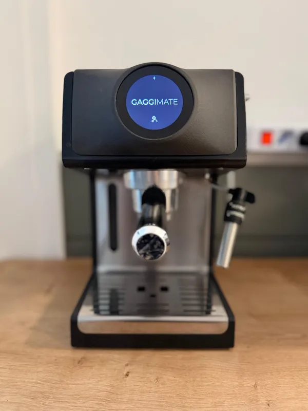
TorxFighter designed the front panel replacement shown at the start of this guide. It’s not free, but it completely transforms the look of the machine by replacing the entire front panel and seamlessly integrating the screen. The author of this guide uses this print and recommends it. Find it here.
Prowler has designed a screen housing for the 2.8” LilyGo (not WaveShare!) screen that mounts on the front panel. Find the model here.
DeLonghi Stilosa
2.8” Screen
Stuart has designed a screen housing for the 2.8” WaveShare screen that mounts on the front panel. Find the model here.
PCB Prints
Internal Mounting Solutions
You can buy a pre-printed low-profile cover from the GaggiMate Shop, or download the model and print it yourself.
⚠️ Mounting your PCB inside the machine is strongly recommended.
External Mounting Solutions
⚡ Please keep your PCB and SSR secure within a housing when your build is done. Leaving them exposed is an electrocution risk.
TorxFighter, creator of the front panel replacement print, has also released a PCB housing that mounts on the back of the machine and holds both the PCB and SSR.
ph has designed and shared another version that also fits both the SSR and PCB, mounted on the back of the machine.
You can buy a pre-printed PCB housing from the GaggiMate Shop, or download the model and print it yourself. Note that this housing only holds the PCB. You’ll need a separate solution for the SSR.
⚠️ The guide does not provide instructions for an externally mounted PCB and SSR. If you go this route, you must drill a hole in the back of your machine.
Before You Begin
Now that you have all the equipment you need, before you proceed, please make sure you prepare yourself and your workspace.
Flashing the Hardware
Flash both the PCB and screen before installing them. It’s much easier to do outside the machine. Follow the instructions at docs.gaggimate.eu/docs/flashing.
Diagram — Wiring
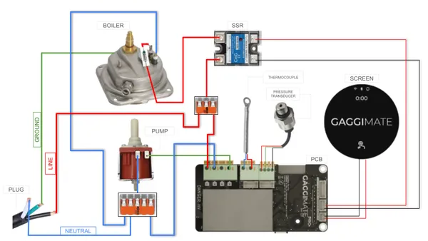
Please ensure you reference the appropriate wiring diagram below as your primary roadmap for this entire project. It might look intimidating, but take your time; we will break down each connection in the guide. The diagrams are your essential blueprint.
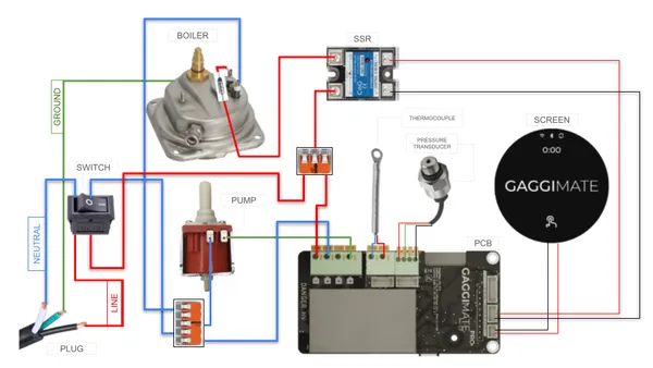
ℹ️ You may install a power switch on the American version of your machine if you wish, but it will require cutting an additional hole in the chassis to support the new switch. This is not covered by this guide. If you proceed with this addition, you must wire your machine according to Diagram B.
Diagram A — No Power Switch
e.g. American ECP & Stilosa models.
Diagram B — Power Switch
e.g. European ECP & Stilosa models.
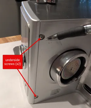
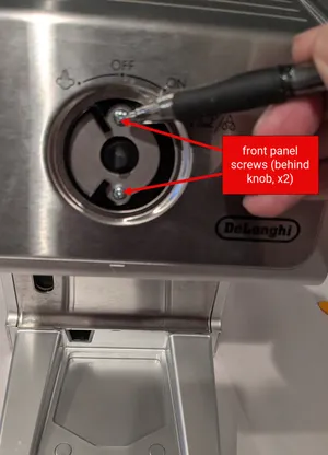
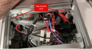
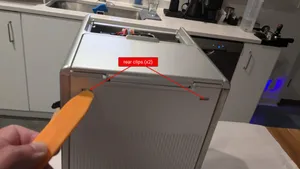
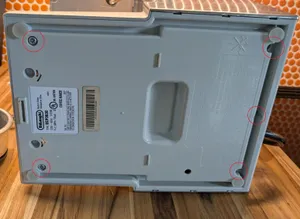
Prepare the Machine
Image credit: lchasemarsh
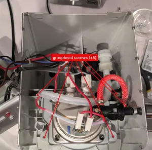
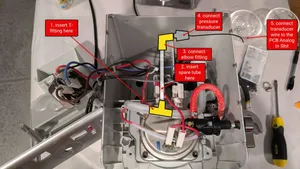
Pre-Wire Planning & Layout
Plan your component layout before cutting any wires. Always measure twice and leave extra lead length to ensure the PCB and SSR can be mounted and connected without straining the terminals.
Recommended PCB mounting location.
Recommended SSR mounting location.
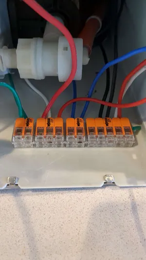
An optional location to mount your WAGOs. WAGOs are small and you have more flexibility with their location.
Wire the Pump
The pump is not polarized. It does not matter which wire connects to which terminal. ↗️Refer to the Wiring Diagram
Connect the Blue Pump Wire
Connect the Green Pump Wire
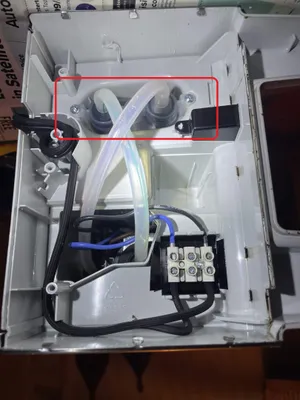
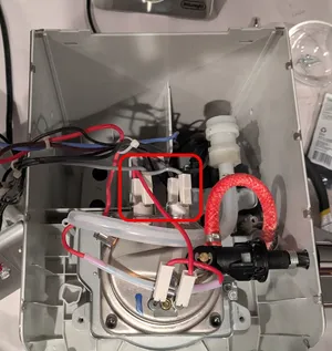
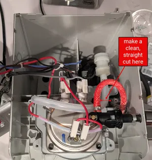
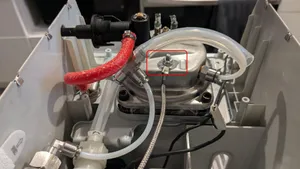
Prepare the Water Line
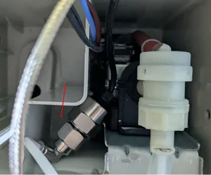
Re-seat the Frame
A correct installation of the Pressure Transducer and fittings will look similar to the image above.
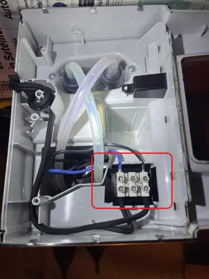
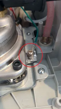
Wire the Boiler
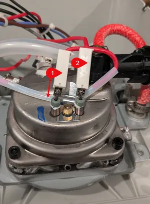
The boiler is not polarized. Note how the fuse is secured to the boiler via the metal clip. When you reconnect the fused wire, secure it the same way to ensure it stays in place and maintains good contact with the boiler surface. ↗️Refer to the Wiring Diagram
The fused wire is indicated by the arrow pointing down from label 1.
Connect the Red Fused Boiler Wire
Connect the Blue Boiler Wire
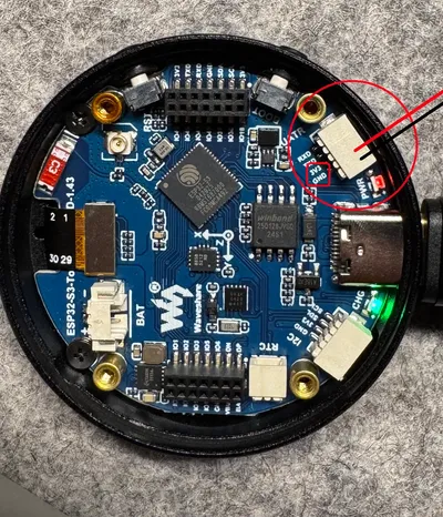
Wire the Screen
This section explains how to prepare a WaveShare screen for connection to the PCB. If you purchased a LilyGo screen, the process will be similar, but wiring may differ. Refer to the documentation that came with your screen for specifics.↗️Refer to the Wiring Diagram
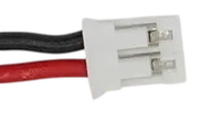
Prepare the 2-Pin Female PH 2.0 Connector
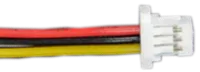
Prepare the 4-Pin Female SH 1.0 Connector
The WaveShare includes 2 of these. You only need 1, but keep the other as a backup.
Prepare the 22 AWG Wires
Prepare the Screen Connection
Prepare the PCB Connection
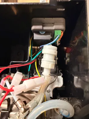
Attach the Thermocouple
A successful thermocouple installation will look like this (rear-view of the boiler).
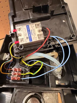
Wire the Solid State Relay (SSR)
Attach the SSR Output-to-Plug Wire
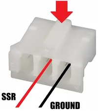
Prepare the 3-Pin Female PH 2.0 Connector
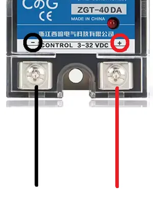
Prepare the Control Wire Ends on the SSR Side
Attach the Control Wires to the SSR
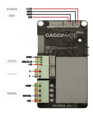
Diagram — PCB Wiring Pinout
Refer to the wiring pinout diagram below as we begin connecting the remaining wires to the PCB. Following the pinout carefully is crucial to ensure proper functionality and avoid damage to components.
Connect the Components
⚡ Keep your PCB and SSR secured inside a housing when your build is complete. Leaving them exposed is an electrocution hazard.
ℹ️ Due to limited space, it is easier to mount the PCB after you finish wiring it.
Wiring the Grounded Power Cord
⚡ Proper grounding is crucial for safety. If you are unsure about any part of this process, please join us in Discord.
Even though the American version is not grounded by default, the grounding-point is there for you to use. While the DeLonghi America engineers chose not to ground the boiler, they also didn’t expect dramatic modification of their machine. The GaggiMate team strongly recommends that you ground your boiler.
On the 3-prong power cord linked in the shopping list, identify the following wires:
Line is black . For the EU machine, it is brown .
Neutral is white . For the EU machine, it is black .
Ground is teal . For the EU machine, it is green and yellow .
With everything connected, plug in your machine and turn it on. If everything is wired correctly, you should observe the following:
If any of these three things do not occur, there is likely a wiring issue. Unplug your machine, review the guide carefully, and retrace your connections to locate and correct the error.
Assuming all three systems power on correctly, visit the GaggiMate website and follow the instructions in the First Start documentation. While there, also review the Configuration and Touch Screen Usage documents to familiarize yourself with the GaggiMate software. Lastly, if you experience any issues, please check the Troubleshooting section.
Final Setup and Testing
Use GaggiMate’s software Auto-Tune feature in the PID Autotune page to generate PID values specific to your machine. This ensures the software can control temperature effectively and accurately.
Before reassembling your machine completely, consider pulling a test shot using the GaggiMate interface. Confirm that there are no leaks.
If everything looks good, if you have no leaks, then you’re ready to reassemble your machine.
Before final reassembly, unplug your machine and take some time to organize your internal wiring using your solution of choice. Verify that no wires are resting directly on the boiler surface where heat could cause damage to them over time. The only wire that may rest on the boiler surface is the fuse-protected wire.
Troubleshooting
The list below contains common issues you might encounter. If your problem is not listed here, please join us in Discord. We’d be happy to try to help you.
I have leaks!
To ensure a leak-free installation, carefully inspect your water line connections.
Check Cuts: Ensure all cuts to the tubing are sharp, straight, and clean.
Check Tension: Short tube lengths can create tension that may cause leaks. It is better to have longer tubes that can sit without tension than to have tubes that are too short and pulling on the fittings.
Seating: Verify each hose is seated firmly into its respective fitting.
O-Rings: Confirm that hoses leading to the boiler and overpressure valve are clipped in securely and that the black o-ring is present and correctly seated.
After starting my machine, I keep seeing a “Temperature error, please restart” message. What should I do?
Test the Thermocouple: Use a multimeter in continuity mode. Touch one probe to the thermocouple end and the other to a terminal wire. If it beeps, it is grounded. You will need to replace it with an ungrounded version.
Check the Outlet: If the thermocouple is ungrounded, try a different wall outlet. The PID controller is sensitive to electrical noise from weak or “noisy” sources like extension cords with USB ports.
I moved it to a different outlet, but I still have the same error. What should I do?
Your thermocouple wires may not be making a tight connection.
Fold the Wires: If using naked wires, fold them over and twist them to give the slot clamps more surface area to bite onto.
EMI Reduction: Consider wrapping the terminal wires in ferrite beads or adding an EMI filter to the power line.
What is that weird repeating “sucking” sound in steam mode?
That is the Steam Assist feature. It uses the water pump to inject precise pulses of water into the boiler while steaming to maintain high pressure and consistent heat. If you prefer to disable this, change the Steam Assist value to 0 in your settings.
Yuck! My coffee tastes underextracted or sour. What’s wrong?
Most machines have a temperature gap between the thermocouple and the grouphead.
Adjustment: Increase the “Temperature Offset” in your settings to raise the target temperature.
Expected Range: It is normal to see an offset of 10–20°C on machines like the DeLonghi ECP.
I am not hitting the pressures I expect.
Unlike electronically-controlled 3-way valves of more expensive machines, the mushroom valve in DeLonghi machines requires at least 4-bars of pressure to open. If your pump pressure is too low, the valve won’t open fully, leading to underextraction. Increase the pressure values in all phases of your preferred profile(s). The best way to determine the exact pressure values for your machine is by using the calibration profile created by cerealkiller, shown below. Copy and paste it into an empty notepad text file, save it as pressure-test.json, and then import it into GaggiMate’s Profile page. Run the profile without a portafilter and observe the brew group. When you begin to see steady water flow out of the brew group, that is the minimum pressure your pump needs to reach to open your valve. You can then set your profile pressures accordingly, ensuring they are above this threshold for optimal extraction.
Click to expand utility profile “Pressure Test JSON”
While there is currently no “consensus best” setting for the DeLonghi, mdwasp recommends starting with a Kp of 32, a Ki of 0.05, a Kd of 42 (i.e. 32,0.05,42), and a Thermal Feedforward Gain (Kff) of 0.6. We strongly recommend using AI to assist you with dialing in a precise PID configuration for your machine. Please visit this Discord channel for detailed instructions on how to leverage AI for precision PID tuning.
What Temperature Offset should I use?
A temperature offset of 15° is a common starting point, but every machine behaves differently and you should measure your actual brew temperature. If you lack a Scace device or a method to measure portafilter temperatures directly, you can use the “flash steaming method” to calibrate your offset. For detailed instructions on this process, please refer to this Discord channel.
Lance Hedrick called this a “meme-machine”. What else can I do?
Yes, he most certainly ▶️did! If you want to go “buckwild,” the community has experimented with:
Trimming mushroom valve springs for lower brewing pressure.
Swapping vibratory pumps for quiet rotary pumps.
Installing boiler diversion plates for better thermal stability.
Drilling the boiler casing for submersible, probe-type thermocouples.
If you need further assistance, please refer to the GaggiMate Troubleshooting Documentation. While the guidance provided here addresses specific concerns relevant to this model, the full documentation covers a broader range of potential issues you may encounter during operation or maintenance.
Congratulations!
Welcome to the world of turbocharged espresso! Now you can extract better than café-quality shots from a compact, affordable machine that rivals the big names at a fraction of the cost.
Acknowledgements
Flavius for successfully being the first known person to install GaggiMate on a DeLonghi ECP, answering a ton of questions, and helping identify the required components.
mdwasp for providing a lot of information and for being the creator of the GaggiMate project.
TorxFighter for doing a lot of tinkering and sharing awesome 3D-prints specific to our beloved little DeLonghis.
Abunchahicks for wiring assistance and general knowledge and helpfulness.
Stuart for technical support and prints.
Prowler for a 2.8” screen print.
odor4fun for sharing his knowledge about the mushroom valve and how to optimize pressure values for better extraction.
cerealkillers for the pressure test utility profile.
The GaggiMate team for their incredible work and contributions.